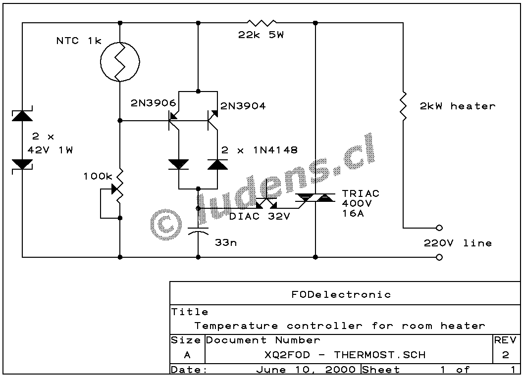
 Here is the
full
resolution version of this schematic. How do you like it? I created
this design just yesterday (2000-6-10, southern winter!), so I'm still
mighty proud of it, while enjoying the regulated temperature in my room
at this very moment!
Notice that this is entirely an AC design. The TRIAC, DIAC, capacitor, resistor, potentiometer and thermistor are all AC devices. I did not have a suitable MOV at hand, so I used two Zener diodes in back-to-back fashion. The poorest aspect is that I don't know of the existence of any AC transistors, so I had to pair two complementary ones, joining the collectors through diodes, thus creating my AC transistor from 4 parts! It works well, but if the transistors are not well matched, this will result in the TRIAC firing earlier in one half cycle than in the other, superposing a DC component on the AC line, which in certain (few) cases can lead to trouble. Try to select nicely matched complimentary transistors!
Let's suppose that a positive half-cycle starts. As the voltage rises, the 22k resistor will feed the circuit. The upper Zener diode will clamp the voltage at 42V, with the lower one just conducting. The 100k pot is adjusted in such a way that the base-emitter voltage is just enough to make the PNP transistor conduct. The capacitor will slowly charge up, reaching 32V sometime within the half cycle. The DIAC will then fire, dumping the capacitor's charge into the TRIAC, which will also fire, and conduct for the rest of the half cycle, keeping the control circuit powered down.
For the negative half cycle, everything will be the same, except that the Zeners reverse roles, and the NPN transistor conducts. The unused transistor in any case stays off, with 0.6V inverse voltage across the base-emitter junction, and its collector insulated by the diode.
If the room temperature rises just a little, the resistance of the NTC will drop a little bit. The small reduction in base-emitter voltage will make the transistors conduct dramatically less current, so that the TRIAC will fire much later in the cycle, strongly reducing the heating power. If the temperature rises enough, for example by sun shining into the window, the capacitor will never charge to 32 V, the TRIAC will never fire, and the heater will stay completely off. On subsequent cycles the capacitor will charge positively and negatively, never accumulating enough voltage to fire the DIAC, eliminating odd-cycle firing, which is a problem in some other designs.
At lower temperatures, the transistors will saturate, firing the TRIAC very soon after the waveform reaches the 42 V level. This affords around 95% of heater power.