GPS-based frequency standard
 In
an electronics laboratory an accurate frequency standard is a very
useful tool. In a ham radio station it's also very useful. Since I run
both an electronics lab and a ham station, and both share the same
room, sooner or later I had to build a frequency standard that would
fit both uses!
In
an electronics laboratory an accurate frequency standard is a very
useful tool. In a ham radio station it's also very useful. Since I run
both an electronics lab and a ham station, and both share the same
room, sooner or later I had to build a frequency standard that would
fit both uses!
There are two good options available at low cost nowadays. One is to
buy a used atomic frequency standard, which is available on eBay
for less than 100 dollars (2013 prices), and build the
necessary
electronics around it to suit one's needs. The other is to buy a used
GPS board, which is available for just 35 dollars, and also build the
necessary electronics around it.
An atomic standard is autonomous, but may need slight tweaking to keep
it accurate in the long run. A GPS receiver depends on the GPS sats,
and antenna, and is subject to ionospheric distortions, but will remain
accurate as long as the GPS constellation continues to exist. The
atomic standard is more accurate in the short term, and the GPS in the
long run.
It would be best to combine both, in the form of a GPS-disciplined
atomic standard! But I left that for a future project. For the present,
I settled for a GPS-based reference.
My main HF radio is a Kenwood TS-450, so I wanted to phase-lock this
radio to the GPS output. This allows using the radio both as an
extremely accurate signal generator, and in conjunction with audio spectrum
analysis software on a PC it can be used as an equally accurate and
ultra sensitive frequency meter, far more resolving and accurate than a
typical frequency counter. The TS-450's reference oscillator runs on 20
MHz, so my circuit has to provide this frequency. I
also wanted a
front-panel reference output on a nice, convenient, round frequency, to
calibrate laboratory equipment, and chose 10 MHz for that.
Originally I intended to make a highly stable ovened crystal
oscillator, and discipline it via the GPS and a microcontroller. But I
found that for all my practical needs, this is overkill. Instead simply
phase-locking a plain, simple crystal oscillator to the GPS output is
good enough! So I did exactly this.
 The
GPS board chosen was the Navman Jupiter-T. It's also known as Rockwell
Jupiter-T, and some other names. This is a GPS specifically optimized
for timing purposes, rather than positioning, although it does deliver
position info too. The big advantage of this model over almost all
others is that it provides a 10 kHz output, in addition to the 1 Hz
output provided by most timing GPS receivers. This 10 kHz signal is
much easier to lock to.
The
GPS board chosen was the Navman Jupiter-T. It's also known as Rockwell
Jupiter-T, and some other names. This is a GPS specifically optimized
for timing purposes, rather than positioning, although it does deliver
position info too. The big advantage of this model over almost all
others is that it provides a 10 kHz output, in addition to the 1 Hz
output provided by most timing GPS receivers. This 10 kHz signal is
much easier to lock to.
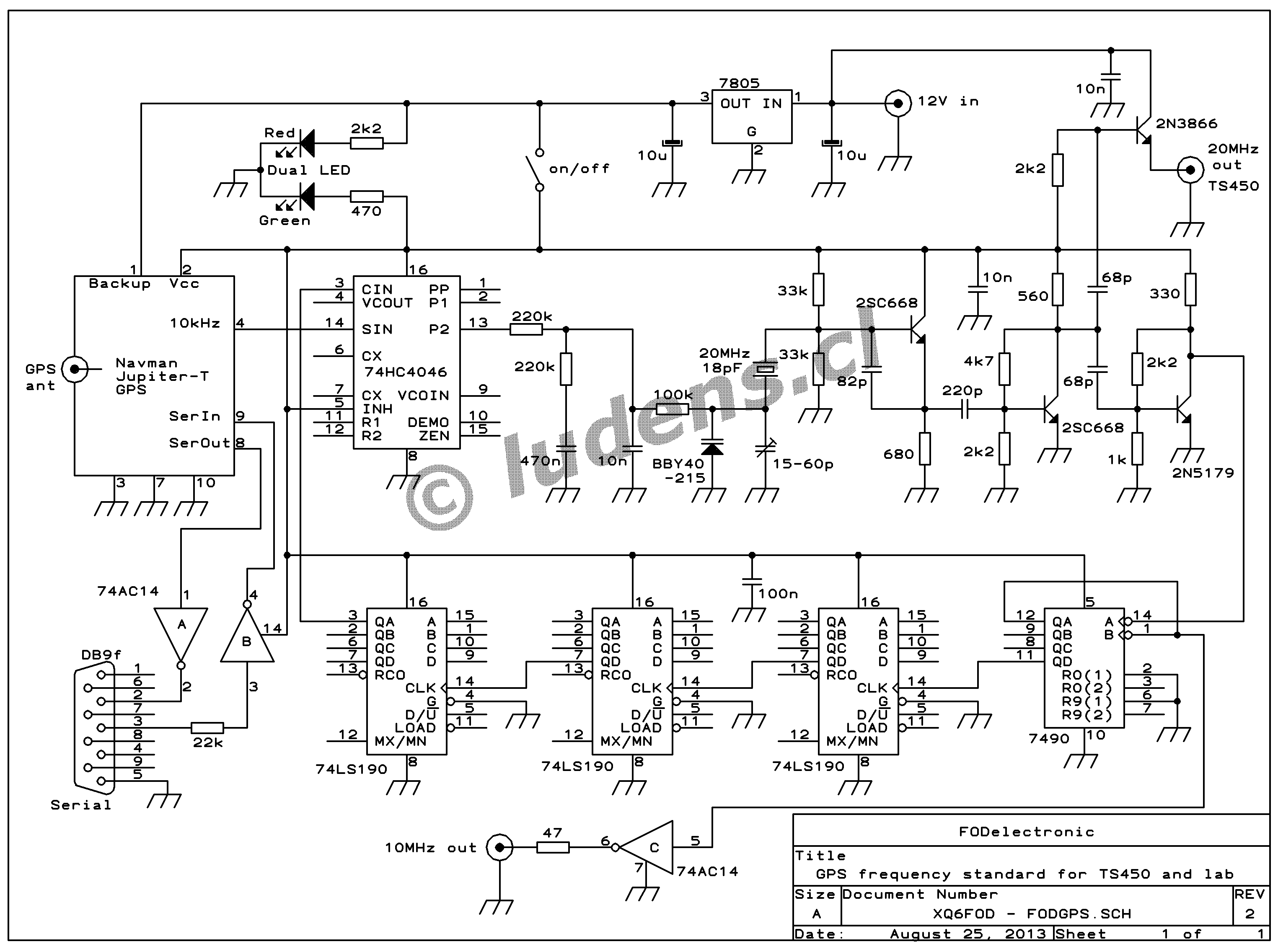
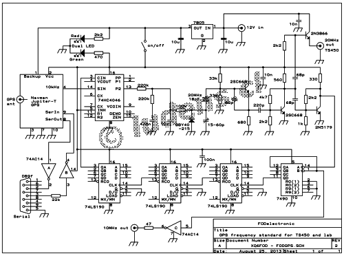
You can click this schematic to get a larger version.
The circuit starts with a voltage-controlled crystal oscillator running
on 20 MHz, having a narrow tuning range of only a few tens of Hertz,
followed by a buffer/amplifier stage. Here the signal is split up: An
emitter follower provides the signal to a jack, for the TS-450
transceiver, while a saturated amplifier provides a rough square wave
to the input of the divider chain. This chain consists of a 7490 and
three 74LS190, for the simple reason that I found them in junked
equipment, so I used them. These burn a lot of power, so it would be
better to use more modern ICs. The divider chain divides by 2000,
providing a nominal 10 kHz to a 74HC4046 PLL chip's phase/frequency
comparator, which compares it to the GPS's 10 kHz output. The chip's
output is passed through a filter with pretty high damping factor, and
used to fine-tune the crystal oscillator's frequency.
A 74AC14 inverter is used as a buffer, to deliver a strong 5V TTL/CMOS
compatible 10 MHz output to the front panel BNC connector, through a 47
Ohm resistor that allows connecting long 50 Ohm coax cables directly to
this output. My choice of providing 10 MHz at this output is based on
my own needs, but the divider chain provides many other frequencies
too, such as 1 MHz, 100 kHz, etc. It would just take a switch to
provide a selectable output.
Two more sections of the same 74AC14 inverter chip are used as buffers
and sort-of level converters, to allow talking to the GPS receiver from
a PC, via a common RS-232 serial port. This can be used to read the
position, set up the receiver for some special use, but it's not
necessary to use this port at all. Just powering up the GPS board will
make it search for sats, lock to them, and provide its highly accurate
10 kHz output.
My GPS time base is powered from the 12V (or rather 13.8V) that's
available in my shack all the time. When the power switch is in the OFF
position, most of the circuit is powered down, but the 5V regulator
remains running, and powering the backup input of the GPS board. This
keeps the GPS's memory alive, which retains configuration and start-up
data. This isn't essential unless you want to configure the GPS to some
special function, and have it remember that!
The power LED will glow dim red when the unit is off, but the memory
backup is powered; and it will change to intense green when the unit is
on.It might be useful to add some indication whether the GPS receiver
is locked to the sats, and the PLL is locked to the GPS. Maybe I do it
in the future. For now, I watch how the radio comes on frequency two or
three minutes after switching on the GPS! It's pretty
obvious.
Note that the circuit provides the 20 MHz signal to the TS-450
transceiver added to roughly 4.4 volts of DC. This is used to
automatically switch the radio over between using the GPS reference, or
its own internal reference oscilator. I installed a small RF relay
inside the radio, that has a 5V coil. This coil is powered from the DC
provided by my circuit, through a little RF choke, and switches over
between the internal oscillator and the 20 MHz coming in from the GPS
unit. Of course I also had to add a connector to the back of the radio.
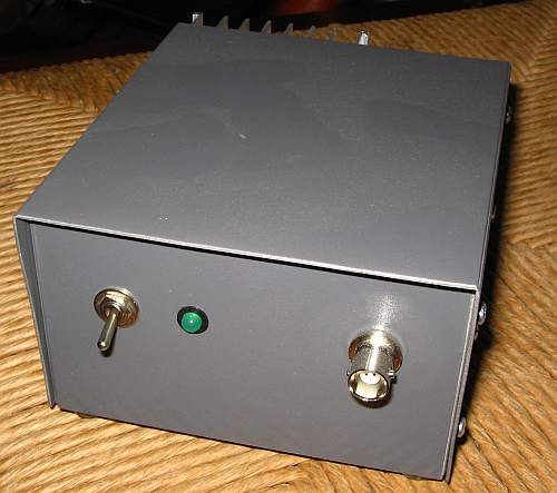
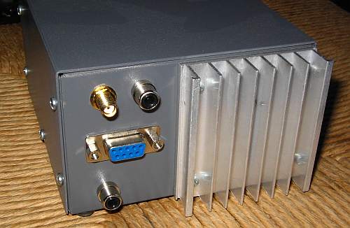 I
built a nice enclosure from 1mm thick aluminium sheet. On the back
side, it has a rather big heat sink for the 5V regulator, and several
connectors: GPS antenna input, 12V input, serial port, and the output
to the TS-450. The front side can be seen at the beginning of this
page, and features just the power switch, power LED, and the 10 MHz
output. In that very particular style I have been practising for over
30 years, this unit has no labels anywhere. It is expected that the
user, and that's me, knows what is what!
I
built a nice enclosure from 1mm thick aluminium sheet. On the back
side, it has a rather big heat sink for the 5V regulator, and several
connectors: GPS antenna input, 12V input, serial port, and the output
to the TS-450. The front side can be seen at the beginning of this
page, and features just the power switch, power LED, and the 10 MHz
output. In that very particular style I have been practising for over
30 years, this unit has no labels anywhere. It is expected that the
user, and that's me, knows what is what!
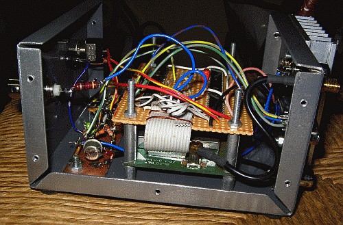 I built the circuit on a piece of
perfboard, except for the crystal oscillator which I built dead-bug
style on a scrap of PCB material. So there is no PCB design available.
The perfboard was stacked atop the GPS receiver board, to make a
compact assembly.
I built the circuit on a piece of
perfboard, except for the crystal oscillator which I built dead-bug
style on a scrap of PCB material. So there is no PCB design available.
The perfboard was stacked atop the GPS receiver board, to make a
compact assembly.
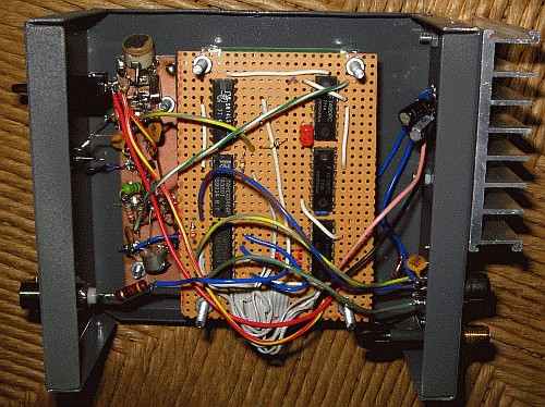 A top view shows the construction even better.
And does it work? You bet! The American Radio Relay League holds an
informal competition about two times a year, during which several
volunteer stations transmit very frequency-accurate test signals, and
all participants have to measure these frequencies as accurate as they
can. Of course this requires having a good frequency standard in one's
station! Even then it's still challenging enough, because the
ionosphere causes Doppler shift to the test signals transmitted on
short wave. And for far-away stations like mine, located in Chile,
there is the additional challenge of even being able to receive those
signals at all! Despite those difficulties, using this frequency
standard I was able to make the so-called "green line", that is,
measuring ALL of the test signals to an absolute accuracy better than
one Hertz, with all uncorrected ionospheric effects included in the
error. My actual average error for all six signals was just 0.07 Hz,
with the worst case error being 0.22 Hz, on a very weak, barely audible
signal. These are signals transmitted between about 3.5 and 14.2 MHz,
so that's pretty accurate! See the official results here.
These are for the April 2013 Frequency Measuring Test. I'm XQ6FOD,
right at the end of the page. Note how few stations there are from
outside North America.
So, this thing clearly works!
Back to homo ludens electronicus.