Dynamo Current and Voltage Regulator
 Up into the 1960s,
every car and almost every other machine with a low voltage electrical
system had a dynamo, also called DC generator. After that time, silicon
rectifiers became widely and inexpensively available, causing a universal
switchover to three-phase alternators with internal rectifiers, which have
many advantages. But even in our days, some old dynamos remain in service,
despite their problems. Often they can be found in antique cars, on boats,
tractors, motorcycles, you name it.
Up into the 1960s,
every car and almost every other machine with a low voltage electrical
system had a dynamo, also called DC generator. After that time, silicon
rectifiers became widely and inexpensively available, causing a universal
switchover to three-phase alternators with internal rectifiers, which have
many advantages. But even in our days, some old dynamos remain in service,
despite their problems. Often they can be found in antique cars, on boats,
tractors, motorcycles, you name it.
Many owners have long ago replaced their dynamos by alternators, but
in some cases that's not an attractive proposition: Antique cars loose
originality if the dynamo is taken away. But my friend Germán had
a more peculiar problem: He bought a sailing yacht which has an old Volvo
Penta Diesel auxiliary engine, and this engine comes with a Dynastarter!
This is a combination starter motor and dynamo. It's basically a 12 Volt
compound motor that is used as such for starting, and as parallel-excited
DC generator when the engine is running. It's coupled to the engine with
two parallel V-belts. For starting it gets its current through a large
relay, and as a generator it used the traditional setup with a voltage
regulating solenoid, a current regulating solenoid, and a reverse current
relay - a system that is very failure prone and has burned out the dynastarter
several times.
So Germán wanted a fix. Either something that makes the dynastarter
reliable, or else a complete change to a separate starter and modern alternator.
Certainly the latter is the better solution, but it's hard to implement,
because this engine doesn't lend itself to the easy installation of a starter
gear. After I went with him on a nice sailing trip in winter 2004, and
with the promise of another trip to the San Rafael Glacier, I couldn't
do less than design and build a tailor-made electronic regulator for his
dynastarter, in a sort of last attempt to avoid the large modification
work on the engine!
Since this regulator will work just as well with a standard dynamo,
and not finding any similar design anywhere in the web, I decided to put
this project on my web site immediately after completing it. Certainly
people out there are looking for such a regulator! So, here it is, for
all you who are locked into using old electromechanical technology, but
not afraid of helping it with some modern electronics!
From the practical point of view, dynamos are different from alternators
in two very important aspects. Firstly, when an alternator isn't rotating,
it won't take any current from the battery. But if a dynamo isn't rotating,
it would drain the battery flat very fast, and very possibly burn itself
out in the process! So, electromechanical dynamo regulators disconnect
the dynamo from the battery as soon as the current starts flowing
in reverse, a delicate and all-important task that often fails to work,
and kills dynamos. In the modern world, of course, we have diodes, and
putting a single big diode in series with the dynamo output solves this
problem once and for all time.
Secondly, dynamos are not self-limiting, while alternators are. When
an alternator runs faster, higher voltage is induced, but also the frequency
of the AC is higher. Since there is a large inductance in the windings,
the reactance increases with frequency, the two effects roughly compensate,
such that a correctly designed alternator can never deliver a dangerous
current! It limits its output current to a safe value, regardless of RPM.
Dynamos instead just don't have this nice feature. As long as there is
enough mechanical drive power, they will deliver whatever current a discharged
battery can take, and will easily self-destroy if the current isn't limited
externally.
Voltage regulation, on the other hand, can basically be implemented
in the same way for dynamos and alternators. So, a dynamo regulator is
basically an alternator regulator with additional current regulation and
reverse current blocking.
So far, so good. Let's go to the details.
 In the typical
dynamo charging circuit, B+ and B- are the battery connections. D+ and
D- go to the dynamo brushes, while DF is the field connection, with its
other end returned to D+ inside the dynamo. Please note that not all dynamos
return the field winding to the positive output! My regulator circuit,
as shown here, works only with dynamos connected in this way. For
further clarity, here's the internal wiring of a standard dynamo. A dynastarter
is just like this but with an additional field winding added, connected
from D+ to an additional terminal, which is used to apply battery current
for starting.
In the typical
dynamo charging circuit, B+ and B- are the battery connections. D+ and
D- go to the dynamo brushes, while DF is the field connection, with its
other end returned to D+ inside the dynamo. Please note that not all dynamos
return the field winding to the positive output! My regulator circuit,
as shown here, works only with dynamos connected in this way. For
further clarity, here's the internal wiring of a standard dynamo. A dynastarter
is just like this but with an additional field winding added, connected
from D+ to an additional terminal, which is used to apply battery current
for starting.
In the regulator schematic I have provided B- and D- connection points,
but of course the two are the same thing: System ground. On the real life
implementation I just named all ground connections D-, following the standard
used on the boat for which the regulator was built.
You can print out this schematic, so you don't have to scroll up and
down the page while reading the explanation. Clicking on the schematic
will bring up a 300dpi version for high quality printing (as long as your
browser can handle the file size... Otherwise right-click, save to disk,
and print from there).
 Let's
start analyzing the circuit in idle condition, when the engine is stopped.
The battery voltage at B+ cannot pass to D+, because D1 blocks it. D+ is
at ground level, because of the low resistance of the dynamo between D+
and D-. Q1 is biased off, which leaves the negative side of the entire
OpAmp circuit floating. So the complete control circuit will float at +12V,
and in this way will bias Q4 fully on. Q4 then holds DF down to ground,
ready for dynamo startup, and for using the dynastarter as a starter.
Let's
start analyzing the circuit in idle condition, when the engine is stopped.
The battery voltage at B+ cannot pass to D+, because D1 blocks it. D+ is
at ground level, because of the low resistance of the dynamo between D+
and D-. Q1 is biased off, which leaves the negative side of the entire
OpAmp circuit floating. So the complete control circuit will float at +12V,
and in this way will bias Q4 fully on. Q4 then holds DF down to ground,
ready for dynamo startup, and for using the dynastarter as a starter.
There will be no power consumption other than the very low leakage of
some components. Q1 is off, D1 and D5 are reverse biased, Q3 is off, D7
stays far below its conduction voltage, Q4 has an insulated gate, C1 and
C8 supposedly don't conduct DC... Actually, the leakage in C8 is the main
current drain, but this leakage gets down into the microampere range when
the circuit is connected permanently to the battery. So, this circuit consumes
essentially no idling current, while keeping DF grounded for easy dynamo
startup.
When the dynamo starts rotating, it will self-excite through residual
magnetism. The very low voltage initially generated (typically 0.2V) causes
a small current to flow in the field winding, through Q4. This increases
field strength, the generated voltage goes up, and soon we have a working
dynamo. As soon as the voltage gets to about 6V, Q1 will switch on and
pull the negative side of the OpAmp circuit to ground. The yellow LED will
light, and the whole regulator circuit gets alive.
Let's see what happens when the dynamo is putting out about 12V. Q1
is on, the yellow LED is on, but the voltage is not high enough to start
charging the battery, which might be near 12.3V. Pin 13 of the current
comparator U1D will be at roughly 10.4V, while pin 12 will be about 0.15V
lower. Thus, pin 14 will be essentially at zero, and the red LED will be
off. Pin 2 of the voltage comparator U1A will be at 4.25V, so that
D4 is reverse biased. D5 too is reverse biased, since its anode is at 3.9V.
Pin 3 of U1A is at a regulated 5V. So, pin 1 is at a high positive voltage,
close to the battery voltage, and the green LED is off.
U2C is an oscillator that runs at roughly 100Hz. It produces an approximate
triangle wave across its timing capacitor C5, which is used as a reference
for the pulse width modulator U1B. Its pin 6 will constantly vary between
one third and two thirds of the battery voltage. Because pin 5 is held
up by U1A, far above 2/3 of the battery voltage, pin 7 will be high too,
and through Q2, Q4 will be kept on. So the dynamo can run at full field
current.
Let's assume that now the operator throttles up the engine. An unregulated
dynamo would now far exceed its current rating, and burn out if the condition
lasts long enough. But in this circuit, as soon as the voltage drop on
R1 reaches 0.15V, current regulation sets in. Let's assume that the dynamo
is charging 20A, with the battery voltage at 13V, and see how this condition
is maintained:
The voltages at pins 12 and 13 will be almost exactly equal. What little
difference appear between the battery voltage and the junction of R2 with
R5 will be amplified by a factor of 1000 by U1D. So, a little variation
of the current around the 20A set point causes a rather large variation
of the voltage at pin 14. When this voltage is above roughly 5.5V, it will
make D4 conduct, and raise the voltage at pin 2 of U1A. The red LED will
be on.
When pin 2 reaches the 5V present on pin 3, pin 1 will start going
down, at a slew rate set by C4, the basic timing capacitor of the control
loop. The larger the current excess, the faster the control loop will act.
The voltage on pin 1 will end up somewhere between 1/3 and 2/3 of the battery
voltage, so the green LED will be on, and U1B will produce a square wave
at pin 7, its duty cycle being a function of the voltage at pin 1. R19
and R20 give U1B Schmitt trigger action, so that the switching will be
as fast as possible, and very clean. The square wave will drive Q4 quickly
on and off, thanks to the emitter follower formed by Q2 and Q3.
While Q4 is on, the full dynamo voltage is applied to the field winding,
and its current increases in time, according to the winding's inductance.
When Q4 switches off, the inductance of the field winding keeps field current
flowing, with the circuit being closed through the freewheeling diode D8.
The current will decrease in time, until Q4 switches on again. So, the
voltage at DF is a square wave, while the current through the field winding
is essentially DC with a small triangle wave component mounted on top.
Any variation in RPM will cause a tendency to change the current, which
will make the circuit react, adjusting the duty cycle of the field winding
drive to keep the output current constant.
As the battery is charged, its voltage will slowly rise, until reaching
about 13.9V. At this level, the voltage at pin 2 of U1A reaches 5V, without
needing any help from the current sensor circuit. The control loop will
then control the field duty cycle to maintain a constant 13.9V, while the
current will drop, making pin 14 go down and the red LED go off. The green
LED will remain lit.
As long as the dynamo remains rotating fast enough, the circuit will
keep regulating the output to 13.9V or to 20A, depending on load demands.
It will never allow any of these two values to be exceeded. When the RPM
of the dynamo are too low to maintain regulation, the circuit will just
let it generate at full field current.
When the engine is shut down, D+ drops to ground, Q1 switches off, the
entire circuit powers down, and remains off until the next use, with Q4
appropriately biased on.
Various notes
This regulator operates with a rather slow time constant when in
voltage regulating mode. The time constant is given by C4 and the parallel
resistance of R11 and R12. When operating in current limiting
mode, the high gain of U1D makes the time constant a lot faster, and asymmetrical:
The regulator will adjust the output down faster than back up. In the presence
of an abnormal pulsed load, this will make the circuit adjust for an average
current somewhat lower than 20A, protecting D1 and the dynamo. Also, if
the fuse is open, dynamo voltage limiting will have a fast attack time.
The fuse was included mainly as a safety measure against failure of
D1. This diode gets pretty warm, and could conceivably fail if it comes
loose from the heatsink. If it fails shorted, F1 would avoid the destruction
of the dynamo through reverse current. Anyway the risk would be low, because
a failure like this would most likely end up with D1 opening rather than
shorting, but fuses are cheap, so it's not bad to include one...
If F1 is open, the dynamo voltage can no longer be regulated by sensing
battery voltage, and also there would be no current to sense. In order
to keep the dynamo voltage from soaring, D5 will inject some current to
pin 2 of U1A, and so the circuit will now regulate the dynamo voltage,
not battery voltage, to about 16.5V, keeping matters safe until someone
replaces the fuse - hopefully before running the battery down!
D18 and D6 are there only to protect the MOSFET gates against abnormally
high voltage, which could happen when the operator does stupid things such
as starting the system without a battery connected. Otherwise they would
not be needed.
C6 and R23 form a snubber which eats up any transients that could happen
during the MOSFET switching. Most likely this snubber isn't needed, thanks
to the high switching speed of D8 combined with the comparatively slow
switching of the MOSFET, which is limited by the slew rate of the TL084.
C8 might not be needed when the battery wiring is short and direct,
but for safety I suggest to include it in all cases. I added it during
the tests of the prototype, after having the system break into self-oscillation
at 300kHz due to battery cable inductance resonating with C1! This event
was useful to see how fast Q4 can really switch! It produced quite a clean
300kHz square wave... Needless to say, switching at a nominal 100Hz, its
switching losses are essentially nil. Maybe the emitter follower would
not be necessary at all, but surely it adds a bit to efficiency of the
regulator.
The use of Schottky diodes at D1 and D8 was decided because of their
low voltage drop. This means less heat (mostly for D1), and heat is the
worst enemy of electronics, as you know. Standard diodes could be substituted,
but I don't recommend it.
U2 is not a Zener diode, but a precision voltage reference IC.
To answer a very common question I often get: No, you should not
replace it by a standard Zener diode. Zeners are not precise enough. This
circuit avoids the use of potentiometers for voltage setting, because they
are unreliable, particularly in a marine environment. It relies on precision
components to get the correct voltage, and this won't work with Zeners.
If you can't find an LM336Z-5.0, you can use some other 5V reference IC
(also called "reference diode", even if it is much more than a diode).
And no, you cannot use a 7805 or any other three-terminal regulator, because
they would mess up the correct startup of the dynamo: While Q1 is halfways
on, a three terminal regulator would produce a lower voltage on pin 3 than
pin 2 of U1A, which would make the circuit switch off Q4 and interfere
with proper dynamo startup.
Feel free to replace components. I used the IRF540, BS170, 30CT060,
SB360, 2N4124 and 2N4403, etc, basically because I had them. Any parts
with compatible ratings should work as well. Don't replace the TL084, unless
you know very well what you are doing. It was chosen because it handles
high input voltages well, and has a high slew rate. Many other OpAmps wouldn't
work well here, and the TL084 is easy to find and inexpensive.
If you absolutely want to include a potentiometer for voltage setting,
you can make part of R12 adjustable. For example, use a 10k trimpot in
series with a 22k fixed resistor. Likewise, if you want an adjustable current
limit, you can replace R2 by a 200 Ohm trimpot. But a safer way to trim
the voltage and current setpoints is by soldering in some series or parallel
resistors picked to give the desired levels. I did not go to this length,
and just mounted fixed precision resistors.
R1 in my prototype is a parallel combination of two 0.015 Ohm, 5W resistors.
If you can't find resistors low enough to make R1, you can use my old fence
wire trick: Galvanized iron wire is cheap, easy to find, easily solderable,
and has a resistance which is very convenient for making very low value
resistors! I have some galvanized iron wire here which has 1.25mm
diameter, which would equate to roughly AWG 16. This wire measures 0.12
Ohm per meter at room temperature, which is very close (slightly higher)
to the calculated value considering the standard volume resistivity of
pure iron. The only trouble is that this wire is rather strongly temperature
dependent. So one has to design the resistor in such a way that the wire
won't heat up too much. For this resistor, two pieces of this wire in parallel,
each about 12cm long, would be fine.
Whatever you use, factory made resistors or iron wire, be sure to connect
the sensing points right to the resistor. Even a small piece of PCB trace
or wiring can add a considerable proportion to this small resistance, and
your regulator would end up regulating to a much lower current than desired!
If you want to use this circuit for a dynamo of a different current
rating, you can modify the value of R1 so that at the desired maximum current
it will cause 0.15V of drop. D1 and F1 should be adjusted to suitable values.
The rest of the circuit can most likely remain the same.
If you want to use it for a 6V or 24V dynamo, this would require a significantly
different circuit. You can't properly drive this MOSFET with 6V minus the
voltage drop in the driver, and if you drive it with 24V, you might burn
it out.
And if your dynamo happens to have one end of the field winding connected
to the negative side, then too you can't use this circuit directly. You
would need to modify the output section, providing a P-channel switch with
proper driving.
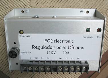
 This was
a very ecological project! Almost all material I used to build this regulator
was recycled from old electronic devices taken from my junk box. The main
organ donors were an old Swedish marine communications receiver, of which
I got about one half; an Atari 1050 floppy drive, which I got almost complete
but nonfunctional and hopelessly obsolete; and a 24V relay-based solar
panel regulator in unknown condition. Since this solar regulator had a
very well suited box and connection terminal strip, I cannibalized it without
even bothering to test its condition!
This was
a very ecological project! Almost all material I used to build this regulator
was recycled from old electronic devices taken from my junk box. The main
organ donors were an old Swedish marine communications receiver, of which
I got about one half; an Atari 1050 floppy drive, which I got almost complete
but nonfunctional and hopelessly obsolete; and a 24V relay-based solar
panel regulator in unknown condition. Since this solar regulator had a
very well suited box and connection terminal strip, I cannibalized it without
even bothering to test its condition!
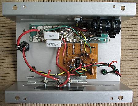
The section of green PCB was cut from the original solar regulator's
PCB. It has the proper mounting holes and connection pads for the terminal
strip, so I used it to install the power components. The control circuit
was built on a piece of perfboard. D1 was mounted to the case using a very
strong clamp, a thin mica insulator, thermal compound and two bolts. Since
it generates a fair amount of heat and is used at 2/3 of its maximum rating
continuously, it needs good cooling to remain reliable. Q4 instead is mounted
with a nylon bolt, mica insulator and thermal compound. It works quite
cool.
The fuse holder was already mounted, so I re-used it. There were some
holes in the box for switches, pots and LEDs, three of which I re-used
to mount my LEDs, even if their position wasn't very logical...
The whole circuit was sprayed with several coats of acrylic lacquer
before mounting it in the box, and then several more coats after mounting.
This creates a tough plastic-like coating that should prevent corrosion
and conductive film forming for many years, even in the harsh maritime
environment where this regulator will be used.
If you can understand Spanish, you might want to read the slightly humorous
Instruction
Manual which I gave the Captain of the yacht for which this regulator
was built.
Updates
After one year of service, an accident happened during engine maintenance. The D+
cable was momentarily shorted to ground while the engine was being started. This resulted in impressive fireworks, a molten wire terminal - and a burned MOSFET in the regulator! While I was replacing the MOSFET, I decided to also reduce the voltage from the original 14.5V to the present 13.9V, by changing R11 from 51k to 47k. I also lowered R10 from the original 39k to 10k, because the original value made current regulation impossible whenever the battery voltage was extremely low! In normal operation that would never happen, but one day my dear friend tried to charge a totally deep-discharged battery after crank-starting the engine, and this resulted in a burned fuse!
The schematic shown here is the updated version.
Back to the homo ludens electronicus
page.