Version #2 of my active HiFi speakers
 Back
in 1991 I built a set of large, active speakers, using a subtractive
phase-linear crossover circuit, with individual power
amplifiers for each driver, that used op amps with wrap-around
transistors biased into expanded class-A. I have used these speakers
extensively, listening to good music for a few tens of thousands of
hours. After 22 years using them, finally the desire arrived to do
something new and better - but not too radically new, since the old
system was pretty good! And "better" is a matter of discussion. In
these 22 years I have learned a few more things about audio and
electronics, but it's debatable how much improvement could be done on
my old system, and specially how audible that improvement is!
Also my current test equipment is much better than what I had 22 years
ago, so I can now measure defects that were hidden to me when I built
the old system. At the end of much thinking, testing and measuring, I
replaced
essentially the entire electronics of my old speakers, along with the
midrange and high range drivers. Just the woofers, the boxes and the
supply transformers
remained.
Back
in 1991 I built a set of large, active speakers, using a subtractive
phase-linear crossover circuit, with individual power
amplifiers for each driver, that used op amps with wrap-around
transistors biased into expanded class-A. I have used these speakers
extensively, listening to good music for a few tens of thousands of
hours. After 22 years using them, finally the desire arrived to do
something new and better - but not too radically new, since the old
system was pretty good! And "better" is a matter of discussion. In
these 22 years I have learned a few more things about audio and
electronics, but it's debatable how much improvement could be done on
my old system, and specially how audible that improvement is!
Also my current test equipment is much better than what I had 22 years
ago, so I can now measure defects that were hidden to me when I built
the old system. At the end of much thinking, testing and measuring, I
replaced
essentially the entire electronics of my old speakers, along with the
midrange and high range drivers. Just the woofers, the boxes and the
supply transformers
remained.
On this page I will describe the new system, and also expose
some
details about the underlying principles, my thoughts about them, and
the problems involved. I will assume that the reader knows my first active speaker system,
so if you haven't read that page, read it now, or you won't understand
where we are coming from.
Be warned that today I'm in verbose mode. This page will be
long.
Active or passive crossovers?
Before I built my active speakers in 1991, I had built several
sets of
conventional speaker systems using passive crossovers. So I know both
sides. And I'm pretty sure that the only
advantage of passive crossovers is that they suit the layout of
conventional music reproduction equipment much better: You have audio
sources (CD player, tuner, computer, media center, and well, maybe a
turntable for the really old fashioned among you); then an
amplifier with integrated volume, balance and tone controls, then the
passive speakers. Simple, tidy, nice.
But bad too.
Such a passive speaker system has many problems. One is that it
is hard to make high order filters in a passive crossover.
Another is that
there are large impedances between the amplifier and the drivers,
causing poor damping. And there is a pretty long cable between the
amplifier and each speaker, adding further impedance. The filter
components cross-couple seriously with the reactances of the
speakers, turning passive crossover design into a tricky business, and
forcing the builder to modify the crossover if any of the drivers is
replaced. All drivers need to be of the same sensitivity, or you have
to use lossy resistance networks to match them. Last not least, the
large inductors and capacitors of a
passive crossover can be quite expensive, unless you are willing to
settle for mediocre components with poor performance.
Using active crossovers, with a separate power amplifier for each
driver, all these problems go away! You can use higher order filters,
damping is optimal because each driver connects through a short cable
directly to an amplifier, the driver reactances don't affect crossover
behavior, you can easily adjust the levels for each driver without
having to accept power loss and poor damping, and the components are
small, easy to get, and inexpensive. The price to pay: One amplifier
per driver instead of one per box, having to build active electronics
(needing a power source) into the speakers, and disrupting
the
traditional layout of music equipment, in that you need no power
amplifier in your equipment rack, but you still need source switching,
a volume control and possibly tone and balance controls.
In my opinion, the advantages of active crossovers far outweigh their
costs. So, for my speaker refurbishment I obviously kept the principle
of active crossovers and three power amplifiers per box.
Linear crossovers, or digital ones?
In recent years it has become not only possible, but entirely
reasonable, to replace a linear crossover, built around active filters,
by a digital one, implemented in a digital signal processor. These DSPs
have large, important advantages! For those of you who don't know DSP,
basically such a crossover digitizes the audio signal (or directly
accepts digital audio from a CD player or computer), does all necessary
filtering and other processing in a specialized microprocessor, then
converts the three audio outputs back into the analog domain, to drive
conventional amplifiers. Or even digitally drives switchmode
amplifiers!
In such a DSP it is easily possible to implement filters that
have
a fixed time delay, regardless of filter curve and cut-off frequency.
This not only allows perfect time alignment of low, mid and high audio
signals, but also allows an optimal impulse response. A typical linear
crossover instead has at best a linear phase response, but inevitably
impulses get smeared out - and the higher the order of the filters is,
the more they smear out. Also with DSP crossovers it's very easy to
implement an adjustable delay at each output, to time-align the
acoustical output of the three drivers. This can also be done without a
DSP, either by offsetting the drivers on the front board, or by adding
analog delay circuits as needed. But the DSP implementation is far more
elegant and easier to adjust than either of the non-DSP ones.
But DSPs are still a bit short of maturity. For drop-in use in a
typical audio system, something close to 24 bit resolution is required,
because we want to
accommodate at least
true 16
bit audio, plus enough headroom for varying volume levels! DSPs
suitable for use as crossovers, that have 24 bit input and output
resolution, are already available, but are quite expensive. Smaller
DSPs with 16 bit input and output are already cheap enough to be
competitive, but these fall a bit short of the required audio
quality level.
So I reluctantly chose a linear crossover implementation, but
I
see this only as an interim solution, until DSPs with sufficient
resolution become available at an attractive price.
Filter order and alignment
In a simplistic world, crossovers are simple things too: They split up
the audio signal into its low, middle and high frequency ranges, and
deliver the three ranges to the woofer, squawker and tweeter
respectively. And that's it. But it is an unfortunate fact that this
world is far too complex to allow such a simplistic point of view to
hold true in practice!
One big problem is that no filter can ever be perfect. A typical low
pass filter used for a woofer might have a reasonably flat response
from zero to about 300 Hz, then it will start to attenuate the signal.
By 500 Hz the response might be 6dB lower than at low frequencies, and
as we increase frequency, it gets progressively lower, until from maybe
2000 Hz upwards the output drops steadily at a rate of 24dB for each
additional doubling of frequency. This would be a 4th order low pass
filter. It's quite usable, but far from perfectly passing low
frequencies and perfectly rejecting everything else!
So we have to splice up the different filters of a crossover circuit in
such a way that the total sound output of the speaker system remains
constant
throughout the audio spectrum. But this is exceedingly hard to do!
If we take the filter above (a 4th order, 500 Hz low pass filter) and
combine it with an exactly complementary filter (4th order, 500Hz high
pass), which will serve as the first filter for the midrange channel,
then we get a behavior that (when properly implemented!) results in a
perfectly flat frequency response of the combined woofer and squawker
outputs, for a listener sitting exactly in front of the speaker box, in
an anechoic room. But not anywhere else! Why is this, you might ask...
Well, it's actually quite simple:
At low frequencies, such as 150Hz, the woofer produces full output, and
the contribution of the squawker will be so small that it is
irrelevant, because it gets only a very tiny amount of signal through
its filter. Likewise at 2 kHz the squawker will be producing full
output, and the contribution of the woofer will be negligible. At
exactly 500 Hz, instead, each of the two filters has a response that is
6dB down. -6dB means that the audio voltage, audio current, and sound
pressure, are all half as much as at 0dB. As a result, audio
power is only one quarter as much as at full output. So we have each of
the two drivers (woofer and squawker) producing half the normal
amplitude, and a quarter the normal sound power, and if all is
correctly
aligned, they will be doing this in the same phase, when taking the
listener as the reference point. When two audio sources are in phase,
their signals don't just add their power, but instead there is an
additional gain of 3dB, coming from directivity patterns that stem from
in-phase and out-of-phase combinations of the sound. As a result, the
sound reaching the listener is exactly as loud at 500Hz, as it is at
150 or at 2000Hz. Likewise, at frequencies close to the crossover
frequency, such as 400 or 600Hz, one of the drivers will
contribute more sound than the other, but still the two will add up in
such a way that the listener gets the exact same sound level. So a
perfectly flat response curve results - although only straight in front
of the speaker!
This type of crossover alignment has been promoted by Sigfried Linkwitz
for many years, and has come to be accepted as one of the best, if not the
best possible alignment. But it obviously does have a big fault: When
you consider the total sound radiated by the speaker, this crossover
alignment results in only half as much sound power radiated at the
crossover frequency, compared to the amount of power radiated at lower
or higher frequencies. In other words, the frequency response of a such
a speaker has a 3dB dip centered on the crossover frequency, when you
consider the total sound power radiated, instead of only the sound
intensity
along the axis of the main lobe!
How important is this? Since I didn't find a convincing, independent
assessment of this, I decided to try it myself. For this purpose I set
up some audio processing software to convert an audio file on
my computer into a "crossovered" version, having three channels. I have
a 4 channel amplifier
in the computer,
so it was easy to take the outputs of these channels and feed them
directly to the three drivers in one of my boxes. So I could prepare
several versions of the processed file, using different filter orders
and alignments, and then test-listen to them, switching between them in
any order desired.
I first prepared one file with the standard Linkwitz-Riley alignment,
using crossover frequencies of 500 and 3000Hz, and digitally delayed
the woofer and squawker outputs by the adequate amounts to obtain
perfect phase alignment for my speakers. This should result in flat
on-axis frequency response, and -3dB holes in the over-all-the-room
response at
each of the two crossover frequencies. Then I prepared a
second
audio file, starting from this same crossovered file, but using the
parametric equalizer in that software to raise the two crossover
frequencies by 3dB, with such a bandwidth that a flat over-all-the-room
response
should result, with 3dB peaks at the crossover frequencies in the
on-axis response. And since it was so easy, I also prepared a third
file, which was simply a trade-off, lifting the crossover frequencies
by just 1.5dB, so that either on-axis or over-the-room the deviation
from the optimally flat frequency response would be at most 1.5dB.
Note that with any of these files, inevitably the frequency response of
a multiway speaker will show deep dips at certain frequencies, in
certain off-axis directions. We can either optimize for the on-axis
response, or for the over-the-room average response, or perhaps for a
single direction that is off-axis, but we cannot make a multiway
speaker that is free of these deep dips, caused by cancellation between
the sound coming from two drivers at slightly different distances to
the listener.
Then I sat there, in front of the speaker, and listened to the three
test files, comparing them -
and trying hard to hear the differences! Then I wandered about in the
room and listened to the three files, trying the same. I was surprised
at how little difference could be heard! Don't get me wrong, there was
a difference, but it was rather subtle - and I absolutely couldn't
decide which of the three files sounded better, or more realistic! In a
blind test, I don't think I would have been able to detect by ear which
of the files was playing.
So, the outcome of this test is that the 3dB dip or hump really doesn't
matter enough to worry about, compared to the other huge irregularities
that any loudspeaker shows, when used in a real room, that is full of
frequency-selective resonances, absorptions and reflections. The
Linkwitz-Riley alignment, while not mandatory, is a
compromise as good as as any, to
my ears.
I then made some more tests. The most important: How important is the
order of the filters? The frequency range near each crossover
frequency is problematic, because two drivers are contributing
significantly to the sound field. By increasing the filter order, we
can make these problematic frequency ranges much narrower, and thus
less problematic. In an extreme case, using ideal "brick wall" filters,
there would be no frequency overlap between drivers, and so the problem
of the deep dips would be gone! On the other hand, having such brisk
hand-over from
one driver to the other may bring about other problems, in
that differences in their
radiation patterns might become more obvious. A smoother hand-over,
produced by lower order filters, might better hide such pattern
problems. And of course there is the problem that analog filters cause
increased delay and phasing problems, as we increase their order, and
this worsens the impulse response - but with my computerized testing
system I was using digital filters, free of this problem! So I could
try high filter orders without entering time smearing trouble.
I prepared test files with second order, third order, fourth order,
eighth order, and to be drastic, hundredth order filtering. I aligned
the filters such that in each case the crossover frequencies were 6dB
down in each filter, thus obtaining a good comparison to the basic
Linkwitz-Riley crossover. Note that with a very high filter order it
becomes highly irrelevant whether the filters cross over at -6dB or
-3dB, because the frequency range shared by any two drivers tends
toward
zero, containing almost no sound power.
The result of test-listening to these files was surprising and highly
revealing: Very clearly, higher order was better, to the point that
hundredth order filtering was shockingly good! It was as if the speaker
had disappeared from the room, and the music was there on its own! I
don't understand yet the details of the acoustical phenomena involved,
but very clearly I lost the ability to detect the position of the
speaker by ear, when using very high order, "brick wall" filtering! I
guess that when we can hear the position of the speaker, our brain does
that by analyzing the direct and reflected sound from the individual
drivers, which allows to locate them in the room. At some
specific frequencies near the crossover frequencies, we get almost no
sound directly from the speakers (the deep dips), but lots of reflected
sound. But when no
two
drivers ever reproduce the same tone, the brain can't do this analysis!
And all the sound bouncing around in the room prevents the
brain
from
locating the speaker simply by normal directional hearing.
In an anechoic chamber this may well be very different, but I tend to
listen to music in my living room, and not in an anechoic chamber...
The sound of this mono file with brick-wall filtering was so promising,
that I processed a stereo music file of a high quality orchestral
recording into a six-channel file, 100th order brick-wall-crossovered
stereo, wired up the 6 outputs of my sound card to the amplifiers in my
old active speakers, and listened to that music. The stereo image that
developed was pretty incredible, although highly sensitive to exact
level balance between the two sides. It was an adventure trip into
musicland. I closed my eyes and listened. I could tell precisely where
each instrument was coming from. After a while, I was literally seeing
the orchestra in front of me! Unfortunately this stereo image did not
work when walking around. I had to sit still, pretty close to the sweet
spot. Level differences of just 1dB between the two speakers
would
make the whole stereo image compress into the area close to
the
louder speaker.
I made another test: Deleting the delays in the woofer and squawker
channels, thus intentionally upsetting time alignment between
drivers. Interestingly, neither the basic sound quality nor the stereo
image seemed to change significantly. So I think that time-aligning the
drivers is somewhat (not very) important in the usual low order
systems, but almost irrelevant when the filter order is very high, even
if in theory it must of course upset the impulse response. May
the audio gurus and other superior beings out there forgive me for this
heretical thought!
After these tests, I knew that I wanted a crossover with very high
order, brick wall filters. This necessarily had to be a DSP
unit.
I looked, asked, searched, considered both board-level kits and
from-scratch approaches using the latest DSP chips I might get,
together with the necessary development tools, but I failed miserably.
My search for a cost-effective DSP platform with true 24 bit codecs
allowing the implementation of truly high order FIR filters turned out
empty. So I decided to use a plain old basic and well proven analog 4th
order Linkwitz-Riley crossover, and keep watching out for a suitable
DSP.
But if you have enough pocket money, you might want to go the DSP
route. For serious $$$ you can get that kind of performance right now
in 2013!
Conventional or subtractive crossover?
As you have read the page about my old active speaker system,
you
know that 22 years back I used a rather unconventional but very
interesting crossover circuit, that was based only on two low pass
filters along with three matched time delay circuits and two
subtracting
circuits. The high pass functions were obtained by taking the full
audio spectrum and subtracting the low frequencies. This approach
results in "automatic" perfect alignment of the high pass and low pass
responses. For example if imprecise capacitor values shifted the
response of a low pass filter, the corresponding high pass response
would precisely track that shift. As a byproduct of the design, the
three outputs of this crossover were perfectly in phase with each
other, and the phase response from input to output was pretty
linear over the whole audio range. This seemed to me like the best
possible crossover circuit, so I used it. But over the years I
discovered several facts about it that make it less desirable than I
thought back then!
The largest shortcoming of the subtractive crossover is that its
ultimate attenuation of far out of band signals depends on the accuracy
of many components! Sure, one can use 1% resistors, even if back in
1991 I used 5% ones, figuring that there was little point in spending
lots of additional money on 1% resistors (quite expensive in those
times), when the best capacitors I could get were 5% anyway. It was
only when I was playing with a new, computerized audio test setup,
that I discovered that my poor tweeters were getting hit by the lowest
bass
frequencies with only about 32dB attenuation! At least these Selenium
tweeters were robust, so they never complained, but let's face it, this
is not a clean way to do things! This was a 4th order crossover, and a
4th order 4kHz high pass filter is supposed to provide more than 100dB
attenuation at 100Hz, right?
Well, since this crossover created the treble channel by taking the
full audio and subtracting the output of the 4kHz low pass filter,
ultimate attenuation depends on precisely matched amplitude and phase
of the low pass filter's output and a time delay circuit. With
5%
tolerance components, we just can't expect very accurate matching! I
did pick the components at assembly time, and so got the actual
tolerances quite a bit closer, but just not enough. A 2.5% difference
in amplitude is enough to worsen the ultimate attenuation to just 32dB,
even with perfect phase alignment! An even smaller amplitude error can
cause that same degradation of the ultimate attenuation, when in
addition there is some phase error - which there certainly is!
So this was a good reason to look for a more conventional,
non-subtractive crossover layout. And this is how I came to "discover"
the already very old work of Sigfried Linkwitz in this field. He
developed a very simple crossover based on complimentary high pass and
low pass filters, that can be built with pretty few parts, of very few
different values, and that interestingly has the very same frequency
response as the subtractive crossover I was using for 22 years!
Only that it will degrade in different ways if the components
aren't accurate: It might suffer from some filter misalignment, but the
ultimate rejection of out of band signals will not suffer. In this
crossover only two of the channels are in the same phase, the third one
is somewhat shifted. This could be corrected by the addition of a
single time delay circuit, but I didn't do this, because
the shift
in this crossover tends to partially compensate the woofer's
excessively backward location, so it is a good thing in my
case!
In addition this crossover requires significantly fewer parts than the
subtractive crossover. This seemed like a very good deal. So I adopted
Linkwitz's crossover, without any more attempts at being fancy.
The bass extension circuit
My speakers use very large, sealed enclosures, and the woofers I use
are extremely soft ones, having an enormously high VAS rating. So even
the big boxes result in a significant upshift of resonant frequency,
along with a rather low Q. Smaller boxes would have produced a higher Q
but with prohibitively high resonant frequency. Back in 1991 I settled
for these big boxes (420 liters total volume in each!), and included a
Linkwitz-designed (there we have him again!) bass response extension
circuit. This gave me essentially flat frequency response from 18 Hz
upward, a feat extremely few commercial speakers achieve. I placed this
circuit at the input to the whole crossover, to avoid disturbing the
phase alignment of the outputs, even if this meant sending the
level-raised deep bass signals through the whole circuit.
Over time things have changed. I have grown old, my woofers have been
wearing out,
loosing elasticity, increasing their damping, and my speakers were
loosing bass response. When I measured what was happening, two years
ago, I was profoundly surprised to find that the frequency response was
starting to fall off at about 120Hz! Far down near 30Hz the Linkwitz
bass extender kicked in and stabilized bass response from there down to
18Hz. I measured everything, and found that the woofers had changed a
lot over the years. Instead of throwing them away and buying new ones,
which would have forced me to re-design the compensation circuit, and
possibly even the boxes, I opted for just redesigning the compensators.
I found that with the extremely low Q that my woofers now had, the
Linkwitz circuit was no longer suitable, and instead I needed a very
simple bass shelving circuit. So I implemented that one, and continued
using
the old and worn woofers.
For version #2, I basically kept the same bass shelving circuit, but I
designed the printed circuit board to accommodate a full Linkwitz
extension
circuit, for the day when I finally have to replace the woofers.
I also decided to change the location of the bass extender. Instead of
being at the input to the crossover, it is now located at the bass
output. That way the amplified deep bass doesn't get to the crossover
filters. The new location of the extender obviously causes some delay
and further misaligns the phase between the woofer and the
squawker, but then anyway I never really aligned the drivers in my
boxes!!! I always intended to do that, but never did. The only real
effect of phase-aligning the drivers is shifting the positions of the
deep dips from one angle to another, hopefully trying to get all of
them into some position where the listener's ears won't ever be, and
that's hard to do for a living room! It's much easier with speakers
that will be used in a concert hall.
The power amplifiers
When I built version #1 in 1991, I spent quite some time comparing
different options for the power amplifiers. They had to be simple,
because I needed to build six of them. Back then I didn't have a good
way to import parts, so I had to build them with whatever parts I could
get in Chile. IC amplifiers were very limited back then. There
were some STK and Sanken hybrid ICs, some of which had very poor specs,
while the others were way too expensive. Monolithic chip amplifiers
were
mostly limited to 12V-powered units for car radios, with distortion
specs in the 0.1% to 1% area, not precisely what I would call HiFi. One
or two amplifiers in 5-pin TO-220 cases were available too, with dismal
performance. On the other hand, fully discrete designs using at least
25 parts each started to be too complex, and still not very good.
Really good discrete designs ran over 40 parts each. I didn't like
that. So I decided to use a novel design (not my own) with an
op
amp driving two power transistors via its supply pins. This circuit is
simple, can be made to bias the transistors into expanded class A (none
of the transistors ever turns fully off), and has quite
respectable performance, much better than the single chip amplifiers I
could get back then. So I used it. It sounded good, and with my test
setup of 1991, the distortion was below the level I could measure, that
is, at least 60dB below the fundamental output, which would be below
0.1%.
Over the years the power transistors' characteristics drifted, and
maybe those of the TL071 op amps drifted too, so that
roughly 8 years ago I had to reduce the value of the base-emitter
resistors, because the idling current was getting too high and the
transistors were approaching thermal runaway, signaled by a suspicious
smell of roasted dust coming from the speakers. The
sound quality never suffered from that, and after lowering the
resistor values, the circuit worked like new.
Now enter 2013. Much better audio power amplifier ICs are on the
market, and thanks to Internet and international credit cards it's easy
to order parts from overseas. So I made a little market study, analyzed
data sheets, compared, and settled for LM3886 chips. They outperform my
old op-amp-based expanded class-A amplifiers by a healthy margin, are
very easy to use, and not too expensive. It's certainly possible to
outperform them using discrete circuits, but there is probably no point
in doing so. If I was reasonably happy with the old amplifiers, the
LM3886's are certainly good enough for me.
The old amplifiers were powered from regulated +/-15V. This was
necessary because the op amps in them were not fit to use the
full
unregulated voltage. But the LM3886 can very easily handle that full
voltage, which is about +/-28V with the transformers I have. Its supply
rejection ratings are also good enough to not require regulated
voltages.
So I powered my LM3886's from the full voltage, obtaining higher output
power. Not that I would really need it for my normal listening
sessions, but when some visitor comes here and starts playing with the
volume control, it's always to good effect when there is a little more
juice available!
Powering the output amplifiers from the unregulated voltage also means
that I could do away with the wrap-around transistors used to reinforce
the three-terminal regulators in version #1. Instead I doubled up the
filter capacitance, to provide enough reserve to allow the power
amplifiers to actually work at full amplitude.
The pop eliminator - gone!
A recurring nightmare of every HiFi enthusiast is a loud !POP!
hitting his poor speaker diaphragms every time he switches on the
equipment! They are bound to blow out some day! So I included
a pop eliminator
in my version #1 circuit, consisting of a simple power-on delayer
controlling a relay that was in series with each driver. This
absolutely eliminated any chance for such popping. The speakers were
connected well after the circuit had settled, and they were
disconnected as soon as the power supply voltage started to go down. So
far, so
good, but I had my worries about the distortion that the non-linear
behavior of relay contacts could introduce. For over ten years all went
well, but then I started getting that kind of distortion, and had to
remove the
relays to clean their contacts. Eventually I had to do it a second and
a third time. One day I decided to try what would happen if I just
soldered bridges across the relay pins? Voilà, there was no pop!!!
These amplifiers came up smoothly enough to cause no pop at all. The
pop eliminator had not been necessary!
The LM3886 doesn't pop either, so I left the de-popper out of version
#2. No more relay contact trouble.
The op amps
In my old circuit I used the TL071 series op amps. Back in 1991 these
were the best audio op amps I could get in Chile. And today they still
are, given that the electronic parts market in Chile is involuting. But
at
least I can order parts from abroad, so I had a wide choice, and the
TL071 series, let's face it, isn't state of the art anymore! I went for
what looked to be a rather appetizing choice: The LME49740
quad
audio op amp. Given that its dual version LME49720 wasn't in stock
when I ordered, I went for the LM4562 instead, which seems to be pretty
much the same thing. The verbose in the data sheet looks a little too
suspiciously like snake oil salesman's prose, but the specifications
are
hopefully true, and mean that these op amps have outstanding
performance.
Of course it's dangerously close to overkill to use such op amps in
this circuit, where they work mostly as unity gain
buffers! I wonder
if
there is any chance to hear the difference in distortion between these
gems and the old TL074, but I can actually measure the difference with
my current test setup, although just barely. The noise instead is very
obviously better with the LME49740, owing not only to its newer design,
but largely to the fact that it is a bipolar device, while the TL071 is
a JFET input op amp, with extremely high input impedance (unneeded in
such a crossover), but higher noise.
Given the lower impedance levels of these devices, both regarding input
and output, I used generally lower resistance values in version #2,
compared to version #1. This also helps in improving the noise level,
by reducing thermal noise coming from these resistors.
Noise was never a practical problem with the old circuit, but I could
hear
background noise when getting really close to a speaker, much closer
than for normal listening. With the new circuit, instead, I can't hear
any noise, not even with my ear directly in front of the tweeter. Yes,
it's overkill to strive for such low noise, but in high end
audio overkill is the name of the game, right?
Differential input
An active speaker like this gets its input signal at line level. This
makes it prune to hum pickup, and when the cables are long,
differential transmission is desirable. Version #1 had single ended
audio inputs, via RCA phono connectors. I used plain common shielded
wire, and grounded the active crossover circuits to the rest of the
audio gear only via the shields of the input cables! The AC supply was
brought in by a two-conductor cable, having no earth. This setup worked
well in my old home, but interestingly after I moved to a new home, I
got a small amount of audible hum! The main difference between the two
homes, in this regard, is probably that the old home had the electrical
wiring laid in steel conduit, while the new home has plastic conduit.
So, no shield, more radiated hum!
To eliminate this problem, in version #2 I configured the input buffer
as a differential amplifier. I kept the same phono connectors, and even
the same simple shielded wires, but grounded the crossovers through a
third conductor in the AC supply cable. This has almost completely
eliminated hum pickup. A little bit remains, and I will probably get
rid of it when I someday drive the audio cables from low
impedance
buffers. At this time, they come directly from the volume control
potentiometer, admittedly a poor setup that also causes some treble
loss! But it has served me well enough for
22 years... And if a buffer doesn't fix the hum, a shielded twisted
pair
surely will, even if it is not driven in true balanced mode, but simply
with one side grounded!
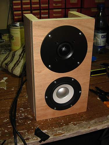
The drivers
Several meters up this page I mentioned my old Selenium 38W89 woofers,
that have degraded very noticeably over the 22 years I have been using
them, but can still provide excellent service, when using a suitable
shelving circuit to compensate for their drooping response resulting
from their now extremely low Q. But the
other drivers have also degraded, in different ways, and I gave in to
the
temptation of replacing them.
When I built version #1 in 1991, I first used Selenium M120 squawkers.
These proved to have an extremely bad frequency response, with 25dB
peaks and valleys throughout the midrange, for which they were
designed! Those drivers had an integral baffle, made of plastic, which
I sawed off in the hope of being able to fix the unusable response, but
it
was in vain. The cones themselves seemed to be at fault, exhibiting
nasty resonances. Their sound was so awfully bad that there was
absolutely no way to use them.
So I raided the TV spare parts stores, looking and listening
for something better. After some searching I settled for a pair of
extended range drivers sold as universal spares for high end TVs of the
time. I never knew what brand they are. The only thing printed on them
was "JAPAN", "10.9 OHMS", and several long numbers which don't tell me
much. But they had an extremely clean, natural sound, and being 4x10",
highly oval units, they combined lots of area for good lower tones with
a narrow horizontal dimension, giving good dispersion of the mid highs.
I liked them a lot. But they too degraded over 22 years of use. Their
diaphragms lost stiffness, and cone brake-up started happening at ever
lower frequencies, hampering their response in the high midrange. So
they had to go.
 I
spent some time comparing specs, reading reviews, and eventually came
across hints pointing at a product of a rather little known German
company, Eton. They have a high end midrange driver that defies some
long standing conventions about distortion in speakers. It's the white
unit you can see in this photo. That white cone is made
from ceramic-coated magnesium, mounted in a highly compliant
soft
surround, and it's smaller than almost any usual midrange
driver.
A midrange woofer? A larger tweeter? A twoofer, or weeter? Can
something as small as this thing work? And specially, can its
incredibly good distortion specs be true?
I
spent some time comparing specs, reading reviews, and eventually came
across hints pointing at a product of a rather little known German
company, Eton. They have a high end midrange driver that defies some
long standing conventions about distortion in speakers. It's the white
unit you can see in this photo. That white cone is made
from ceramic-coated magnesium, mounted in a highly compliant
soft
surround, and it's smaller than almost any usual midrange
driver.
A midrange woofer? A larger tweeter? A twoofer, or weeter? Can
something as small as this thing work? And specially, can its
incredibly good distortion specs be true?
For a few weeks I pondered these questions, made some calculations, and
then I decided to go for it and shell out the hefty sum they want for
it. After all, I did hear some distortion in the midrange of my old
speakers, and much more in most commercial speakers. The human ear is
very sensitive to distortion in the midrange, so that reducing speaker
distortion in this range is one of the most worthwhile investments one
can make in HiFi audio.
My old tweeters, Selenium T800, had extremely good dispersion, thanks
to a cast aluminium diffractor just in front of the dome. But they also
had rather uneven frequency response, probably too thanks to that
diffractor just in front of the dome! So I decided to order new
tweeters along with the new
squawkers. The ones I chose are Eton brand too, with a soft impregnated
fabric dome and big double magnet. The specs of these soft dome
tweeters
seemed better suited to my taste and needs than a magnesium+ceramic
dome tweeter, which Eton makes too, and they have physical dimensions
compatible with the old Selenium T800, reducing the work to be done on
my big boxes.
When the new drivers arrived, after three months of delay in Chilean
customs, I mounted one of each in a test box quickly glued
together from scrap plywood. The squawker sits in a closed compartment
of 0.9 liters volume, which when stuffed with an old sheep wool sock
produces precisely the optimal Qts of 0.71. The other sock is lying
behind the box. The tweeter was mounted above, and then I ran a lot of
tests. I don't need to say much - my measurements agreed with the
published specs to all extents my test equipment covers, and the sound
is extremely clean, natural and transparent.
There is a considerable range of choice for the high crossover
frequency. This squawker has such a good high end response that it
could
be used without a tweeter, in a two-way system, taking care of the
whole range from low mids to the high end. But this applies only to the
axis of radiation. Dispersion of high frequencies inevitably suffers
with a cone of this size.
The tweeter instead starts having a usable response as low as 1kHz, and
by 2kHz it's already pretty good!
I played a lot trying different crossover frequencies, using my
computer-generated crossovered test files. Finally I settled for 3 to
4kHz, but at some times I thought that a bit higher, like 5kHz, was
audibly better when on axis, although dispersion-wise 3kHz was better.
So I purchased capacitors to set up my crossover either for 3.4 or
for 5kHz, just in case I changed my mind later on!
The choice of the low crossover frequency instead was a no-brainer.
Installed in its optimal box, this squawker's flat response starts at
about 300Hz, while my big woofer's flat response ends at about 800Hz.
This pretty much dictates a crossover frequency of about 500Hz, to get
acceptable overlap. That lack of choice is the price one has to pay for
combining a 15" woofer with a 3" squawker! Otherwise there seems to be
no penalty to this combination.
A few words about sensitivity: A huge lot of modern drivers are awfully
weak! They have impressively low sensitivity, often 10dB or more below
what was usual 20 years ago! Even when using an active crossover with
its easily adjustable output levels, one has to be careful when
combining an old, sensitive driver with any new drivers. These Eton
drivers were not too bad in terms of efficiency, compared to many
other modern ones, but still they are far less sensitive than my
old ones. It's not a problem, given that I now have higher output power
from the LM3886 chips, but one wonders what's happening. There are some
modern speakers out there that need no less than a hundred watts of
drive to produce decent sound intensity for home use! That's totally
crazy. It means that speaker efficiency has fallen from its usual 1% to
0.1% and even less! Have a look at old tube radios from the
early
1930's: They have an output power often lower than one watt, but their
speakers
are efficient enough to fill a dancing hall with music!
It looks like the recipe for modern HiFi drivers is rather simple:
Damping, damping, and more damping! At all levels, electrically,
mechanically and acoustically. And if it still isn't flat enough -
dampen it some more!
 Well,
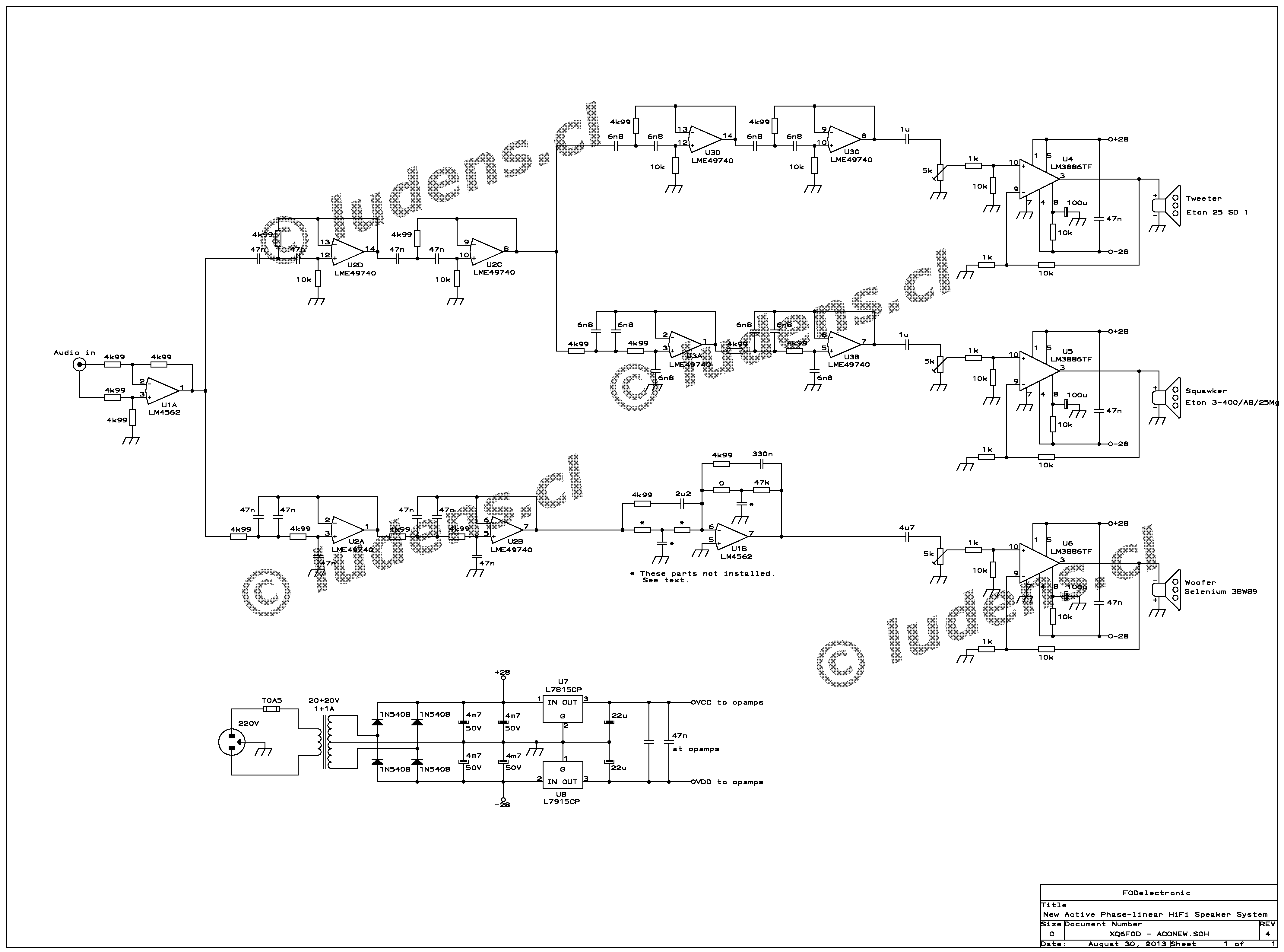
let's go the circuit details. You can click the schematic to get a
larger, legible version. As you will quickly notice, there is
absolutely nothing fancy about the circuit. And to my shame I have to
admit that almost nothing of it is my own design. I only defined a few
details of it.
Well,
let's go the circuit details. You can click the schematic to get a
larger, legible version. As you will quickly notice, there is
absolutely nothing fancy about the circuit. And to my shame I have to
admit that almost nothing of it is my own design. I only defined a few
details of it.
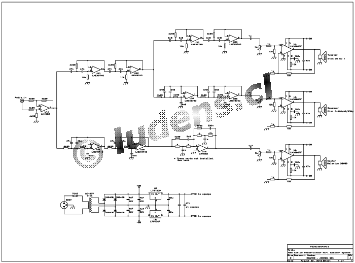
It starts with a basic, standard differential amplifier, straight out
of any basic op amp application note, using U1A. Then follows a
completely standard, fourth order, three way, Linkwitz-Riley active
crossover circuit, using U2 and U3. It's laid out so that the midrange
and treble outputs are in phase, while the bass output is a little
earlier in time. The crossover frequencies are set at about 500 and
3400Hz.
Then comes the Linkwitz bass extension circuit, built around U1B. While
all parts are drawn in the schematic, and room for them is provided on
the printed circuit board, I only implemented a basic bass extension
circuit, sort of a shelving filter with subsonic roll-off, that
suits my aged Selenium woofers. Four components of the full Linkwitz
corrector were not mounted at
all, and instead of another resistor there is a wire jumper, indicated
as a zero ohm resistor on the schematic. If you copy this project, you
must absolutely
measure the
frequency response, or better the Qts and resonant frequency, of your
particular woofers in your particular boxes, and then calculate the
optimal compensation circuit for them. This may be a shelving filter or
a complete Linkwitz bass extender. You can google for "Linkwitz
transform" to learn how to do that. It makes no sense at all to blindly
copy my bass correcting circuit, if your woofers and/or boxes are
different from mine! If you copy this project and you don't know yet
how your woofers respond, I suggest to put in just two equal resistors
(4k99 is fine), one at the input and one as feedback resistor, with no
capacitors (but be sure to mount the appropriate jumpers on the
board!), thus turning U1B into a plain inverting, unity gain stage,
rendering it transparent until you have found out what sort of
compensation you need.
The power amplifiers are totally basic implementations of the
application circuit suggested in the LM3886's data sheet, but using
close to the lowest possible gain at which the IC remains stable, in an
attempt at further reducing distortion and noise. This is about the
right gain to drive the amplifiers just into saturation by applying a
full CD line-level signal to the input, depending of course on the
settings of the potentiometers that adjust the gain of each amplifier.
Note that neither an RC load for supersonic frequencies, nor
an inductor/resistor combination in series, were used in the
amplifier output
circuits. According to the data sheet these are not necessary in this
case, considering that the speaker cables are pretty short, about one
meter at most.
Note also that the woofer is connected with inverted polarity, to
compensate for the phase inversion introduced by the bass extension
circuit.
The circuit is rounded off by a totally conventional, simple and
straightforward power
supply, that provides unregulated but heftily filtered +/-28V (at no
load) to the power amplifiers, and regulated +/-15V to the op amps.
Component notes
Following the style of the Linkwitz-Riley crossover, I tailored the
entire circuit to use very few different component values. It's
much easier and cheaper to buy a hundred resistors of the same value,
than to buy two each of fifty different values! Also it allows to
easily buy a few more than needed, and then measure them all and pick
the more precise ones.
I used 1% tolerance metal film resistors, which are quite cheap
nowadays.
Instead tight tolerance capacitors are still neither cheap nor
easy to find, so I used 5% polyester film caps. I bought about twice as
many caps as needed, and measured them all, sorting them according to
value. Then I used the most precise ones for all those locations in the
filters where a single capacitor is needed, and picked suitable pairs
of capacitors with too high and too low value for those locations where
two capacitors are used in parallel, so that they can compensate for
each other. And the least accurate 47nF capacitors found use too, as
power supply bypass caps!
This kind of filter requires 1:2 ratios of resistors and capacitors in
several places. I had to implement that with paralleled capacitors,
because
exact 1:2 ratio capacitors are hard to find. But for the resistors I
used 4k99 and 10k resistors, which are close enough to the 1:2 ratio.
If you find 5k resistors instead of 4k99, that's fine of course, but
4k7 or 5k1 resistors are not
acceptable substitutes. Of course, you can make a 5k resistor by
placing two 10K ones in parallel.
There are a few higher value non-polarized capacitors in this circuit,
1uF, 2u2 and 4u7. These too are polyester film caps, not some sort of
electrolytics! And no multilayer ceramics either. Such higher value
polyester caps are widely available
nowadays. 20 or 30 years ago they would have been hard or impossible to
find.
All the ICs that attach to the heat sink, that means the
LM3886's and the voltage regulators, are the fully
plastic-encapsulated versions. They tend to cost about the same as the
exposed metal versions, and simplify mounting. I'm puzzled by the power
dissipation ratings for both types of parts being the same, as if the
plastic layer had no thermal resistance! I don't know if this is a
datasheet error, or if really the thin plastic layer has negligible
thermal resistance. In any case, in this circuit the parts are used
well below their maximum ratings, and I used a large heatsink, so the
fully
encapsulated parts are really best. The schematic gives the exact part
numbers for these encapsulated parts. For the other ICs you must see
for yourself that you get the DIP versions, and not any SMD versions
which you can't fit to this board!
Since I listen to music a lot, I picked high quality electrolytic
capacitors, rated for 6000 hours life at 105 degrees Celsius. At the
actual temperatures they see in this circuit, they should last for a
lot longer than the rest of my life. A scaring thought, frankly, but
it's the pure and naked truth!
If you want to replace the op amps by more common, less esoteric,
cheaper ones,
feel free to do so. But try to get some that are at least halfway
decent! They need to be unity-gain-stable, and need to have a decent
output drive capability. The rest of their features, in terms of noise,
distortion and the like, are pretty much up to what you can find and
are willing to pay for. But high performance quad audio op amps are not
very common, so you may not have much choice. The last resort would be
the ubiquitous TL074 and TL072, but if you can, go for the ones I used!
They are very obviously better.
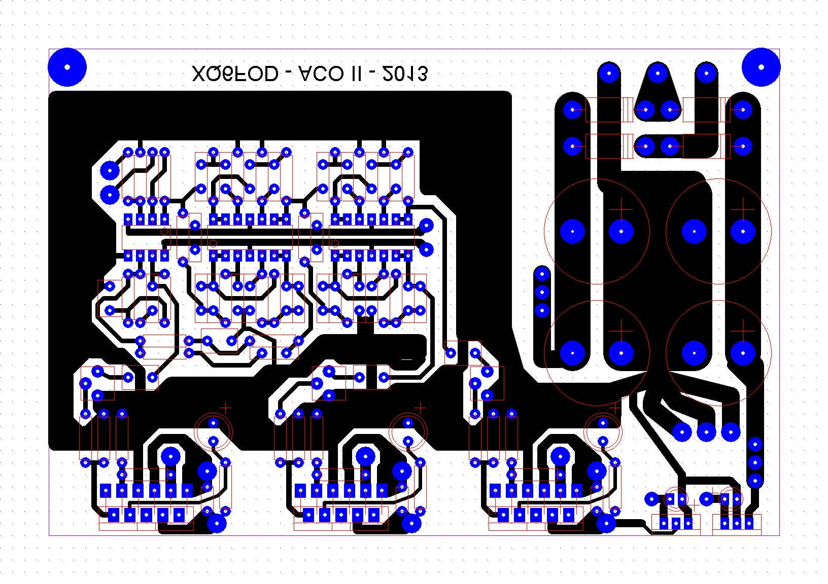
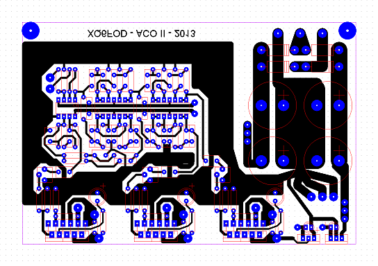 Here
is the printed circuit board layout. You can click it to get a larger,
better detailed version, and to make the board you can get the copper pattern
too. This copper pattern was generated at 5 times the real size, so if
you
tell your printer to downsize it 5:1, it should come out just right. If
your printer software does the classical stupid-clever things they
often do, and
changes the scaling to suit its own taste, you have to override it and
scale it manually. The board is - jubilate, all ye old-fashioned
inch-loving people in the USA! - exactly 6x4 inches! Europeans can use
a standard Eurocard, the design will still fit well enough on it, with
a few millimeters surplus on the sides.
Here
is the printed circuit board layout. You can click it to get a larger,
better detailed version, and to make the board you can get the copper pattern
too. This copper pattern was generated at 5 times the real size, so if
you
tell your printer to downsize it 5:1, it should come out just right. If
your printer software does the classical stupid-clever things they
often do, and
changes the scaling to suit its own taste, you have to override it and
scale it manually. The board is - jubilate, all ye old-fashioned
inch-loving people in the USA! - exactly 6x4 inches! Europeans can use
a standard Eurocard, the design will still fit well enough on it, with
a few millimeters surplus on the sides.
Grounding and bypassing
In version #1, made in 1991, I goofed with the grounding. Somehow I
must have thought that copper is a superconductor. Well, it is not, and
my circuit picked up a slight but plainly audible hum via ground
coupling between the power
supply currents and the driver ground returns, of all things! I had to
cut a
trace and solder a little wire bridge to the same ground blob, but 1cm
further downstream from the filter caps, to get rid of that hum.
In version #2, proudly built in 2013, with the builder being 22 years
wiser, I decided to try not to goof - or at least not as obviously!
Anyone who has been into audio design for more than a month has
certainly heard about star grounding. The idea is simple enough: Run
each and every ground return of your circuit via a separate,
independent
conductor, to one, and only one, central ground spot. That way there is
no chance at all that two parts of the circuit will cross-couple by
sharing a common ground return that has some resistance!
But
as soon as you realize that a simple circuit might have dozens of parts
connected to ground, and a more complex one might have hundreds, this
recipe somehow ceases to be practical!
There is another camp of audio cooks. It promotes a different recipe:
Use a ground plane, made of thick copper, and ground your stuff
wherever you want on that plane. The very low resistance of the ground
plane will
reduce cross-coupling to insignificant levels. Sure, if you really can
find a
printed circuit board with 3mm thick copper on one side of it, that
will work just fine! But I couldn't find such board material... and the
usual copper cladding thicknesses don't cut it, when we get into the
high end audio world where a signal-to-hum ratio of 100dB is considered
to be poor.
I settled for a mixed approach, which you can easily see in the board
layout: I made a star ground for the high current lines, which are just
the
center point output of the power supply and the ground returns of each
of the
three drivers. And I made a reasonably low resistance ground frame for
all of the low current ground returns, assuming that for these low
currents the copper resistance approaches zero closely enough.
All
these low current grounds together connect to the star point via an
additional line. The voltage regulator ground returns are spliced into
this line too, steering for a middle point between the star center and
the small signal ground.
This approach works well enough, it seems: I get no detectable hum, and
I didn't need to cut up traces and re-route connections!
But power supply bypassing remains a conflictive thing. Most circuit
designers are absolutely automatic in this: They place a big, nice,
bypass capacitor between each supply line and ground, as close
as
possible to each IC - and the data sheets and application notes even
recommend this practice!!! But when you look at the waveform of the
current flowing on the supply lines, you will see that these are
extremely distorted versions of the audio signal, since they are
basically the half-wave-rectified copy of them! These currents have
about 30% harmonic distortion. When you place a big bypass cap between
such a supply line and ground, a portion of this heavily distorted
current flows through the bypass cap into your ground, and if that
ground isn't made of a superconductor, or of ultra thick copper, you
will see some of it coupling into the circuit's signal lines!
That
makes a great way of turning a 0.003% distortion amplifier into a 0.1%
distortion one.
Sure, since you would be bypassing both
supply lines, hopefully into very closely neighboring spots on the
ground plane, you should get a full copy of the signal pumped into that
spot, at low distortion. But how close can you make the two grounding
spots for the two bypass caps? And how well matched will the two caps
be, specially if they are electrolytics, with +80/-20% tolerance
rating? With any such solution it's to be expected that a lower, but
still not negligible amount of distortion will show up on the output,
because of this power supply bypassing!
But this leads to a further point: If you would make the ground points
of the two bypass caps as close together as possible, and match the
caps as
well as possible, your goal is basically getting as little current as
possible from the bypass caps into the ground. So why not disconnect
them entirely from ground, and use just a single bypass capacitor
between the two supply lines, near each chip?
Some people might say that amplifiers, specially op amps, might
self-oscillate if not bypassed to ground. I wonder why they say this?!
After all, op amps are very often used in single supply applications,
where there is no ground at mid-level. The op amp has no idea whether
it's operating in a single supply or dual supply circuit! It only sees
the total span from Vcc to Vdd, and all the signals dancing around
inside that span. It doesn't know at what level is ground. It should
feel perfectly well with just a single
bypass cap between rails, and nothing to ground.
So that's exactly what I did. Both for the op amps and for the power
amps, there are local bypass caps only between supply pins, and none to
ground. The only bypassing to ground happens via the power supply
filter capacitors, which is safely on the other side of the star ground
point. In addition to that, those local bypass capacitors are small,
just 47nF. They don't need to be any bigger, because for radio
frequency above a few megahertz these are at least as
effective as a large
electrolytic cap, and lower frequencies anyway see almost no impedance
along the wires to the main filter caps!
As far as I can tell, this approach works perfectly.
 Phew!
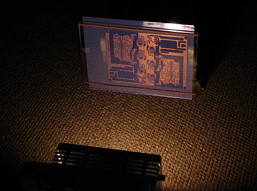
Let's cool down our brains now, and relax watching this nice view of
the printed circuit boards getting exposed. I doubled up the board
design to make the boards for both of my speakers at the same time.
Here you can see a sandwich formed by the sensitized, copper clad
board, and the positive printed by my Canon inkjet printer on
transparent film, between two glass plates, held together by two rubber
bands, and propped up against a stack of antique electronics
books.
Phew!
Let's cool down our brains now, and relax watching this nice view of
the printed circuit boards getting exposed. I doubled up the board
design to make the boards for both of my speakers at the same time.
Here you can see a sandwich formed by the sensitized, copper clad
board, and the positive printed by my Canon inkjet printer on
transparent film, between two glass plates, held together by two rubber
bands, and propped up against a stack of antique electronics
books.
The lamp is a 150 watt metal halide beamer, that produces enough near
UV to expose the photoresist in barely one minute, at this distance.
Then comes development in diluted caustic soda, etching in warm iron
perchloride, cutting to size, sanding the edges, drilling,
stripping the photoresist, and covering in solderable varnish. The
usual dance every electronician knows step by step.
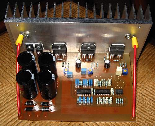
Here
is a repeat of the photo you saw right at the beginning of this
article, roughly three hours ago and ten meters up this page, and which
you have since forgotten, so that I can show it again. It shows the
mostly assembled unit, still lacking the parts of the bass extension
circuit, and all the wire jumpers.
I would like to note that this board is fiberglass, FR4 type, even if
its color looks strangely brown in this photo, almost like Pertinax.
It's less greenish than most other fiberglass boards, and highly
translucent, so that the light brown chair on which I placed it, and
the reddish copper, make it look like this!
And now I have to admit that I did goof a little bit, after all: I
somehow misinterpreted the drawing in the data sheet, or maybe it was
not accurate. As a result the LM3886 chips ended up about 1mm separated
from the heat sink, and I had to bend their pins to fit. It's not
terrible, but shouldn't have happened!
By the way, whenever installing components that are bolted to a heat
sink and soldered to a board, the correct sequence is to first bolt them to
the heatsink, and then
solder them! If you do it the other way around, you can place
such a large stress on the pins, that eventually a solder
joint will crack, a
trace will lift, or even a pin can break, outside or inside the
encapsulation!
I used high quality thermal paste, but any decent thermal
paste is good enough for this application. The LM3886 chips work at a
very comfortable level, and the regulators actually wouldn't even need
to be heatsinked...
The nice big heatsink was bought at heatsinkusa.com. It's big overkill
for the levels at which I listen to music, but as said (how many meters
up this page?), high end audio is all about overkill!
The thick red wires serve no electrical function. Their only reason to
exist is providing mechanical stability. The board is joined to the
heatsink only through these wires, and the terminals of the five power
ICs. Since there is nothing particularly heavy on the board, this
should work fine, even in the long run.
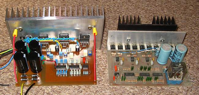 The
king is dead, long live the king!
The
king is dead, long live the king!
At right is one of the version #1 units from 1991, at left is one of
version #2 from 2013. They aren't terribly different, right?
The new unit is now essentially complete, with the bass extender parts
fitted, and the wire jumpers in place. And here I go again, with yet
another long-winded explanation:
Power supply wiring
As already mentioned, the power supply current on each rail is a
half-wave-rectified copy of the output signal, so it carries very high
distortion. If such a line magnetically couples to a small signal line,
this will increase the distortion at the output. To prevent this
problem, I largely avoided routing power supply lines on the
board.
Instead I made them with jumper wires. This provides two means for
reducing such induced distortion: Firstly, by tightly twisting together
the two supply lines going to each amplifier, so that they behave
magnetically as a single line carrying the total current, which only
has low distortion. And secondly, by running these twisted wires high
above the board, through thin air, well separated from any other parts
or traces.
I did this with the supply lines to each of the three power amplifiers,
and also with the 15V supply lines going to the op amps. Only for the
supply bus running along the op amp I did not use this technique. There
the two lines run side-by-side right under the op amps. The distorted
audio currents they carry can reach about 2mA. I hope that this is low
enough to cause only negligible levels of distortion by induction into
signal lines, but I haven't calculated it.
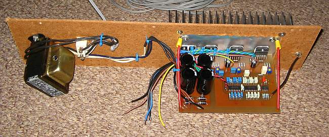 And
here you can see the new board, mounted on the perforated chipboard
back cover of the electronics compartment of my speaker box. You can
see the power transformer, mounted as far away as possible from the
sensitive parts of the circuit, and in a position that minimizes the
stray field at the circuit.
And
here you can see the new board, mounted on the perforated chipboard
back cover of the electronics compartment of my speaker box. You can
see the power transformer, mounted as far away as possible from the
sensitive parts of the circuit, and in a position that minimizes the
stray field at the circuit.
The power cable is still the old, two conductor one. I had yet to buy
some three-conductor cable to replace this, when I shot the photo.
The color-coded output wires for the speakers were later soldered to
the speaker wires, and covered with pieces of insulating sleeve.
At the end, a surprise
When trying out such a new circuit, one expects all sorts of strange
things, such as smoke of assorted colors, self-oscillations, some very
nasty distortion, or at least a reversed driver connection that causes
some
awfully strange sound. But with this circuit nothing of all that
happened. It just worked, as it was intended to, with extremely low
noise and distortion, and overall excellent sound quality in every
regard. I was ready to judge this new creation a boringly tame little
pet, and a
complete success, when I happened to get a call on my cellphone - and
the trackatrackatack-tack-tack-trackatack-tack-trackatrack-tack
in
my HiFi speakers was far louder than the phone's ringing!!! That was a
nasty surprise. The version #1 circuit with its old TL074 chips was
perfectly immune to cellphone interference, but this new circuit with
top-of-the-line, modern audio ICs was fancying itself an
UHF radio receiver!!!
Thinking of it, it's quite obvious. The TL074 uses JFETs at the inputs.
They can take two or three volts of radio frequency signals before
starting to rectify and detect it - if they do at all. Bipolar inputs
instead, like the LME49740 have, are biased just into
conduction, making highly effective
rectifiers for any signals of a frequency high enough that they can't
properly following it! And being modern chips, the structures on them
are extremely small, making them able to detect signals far into the
UHF
spectrum.
I made some tests, and found that both the power amplifiers and the op
amps are picking up RFI. Apparently the LM4562 is far less sensitive to
RF than the LME49740. And the circuit is picking up the RFI right on
the board and components - even with input and outputs disconnected,
except for one small speaker connected directly to the pigtails, and
the input shorted, the circuit picked up the cellphone signal as
strongly
as with everything connected.
At first I suspected my novel bypassing scheme, that has no caps to
ground except in the power supply section. I added bypass capacitors to
ground at all the usual locations. It didn't help at all, so I removed
them again.
Then I tried adding small caps across the IC inputs. I used values like
47pF, which clearly reduced the interference, but did not completely
eliminate it. But they affected the response of the filters, of course,
and larger caps started to cause stability problems.
Probably the best way to fix the RFI is by the old and proven method of
shielding the circuit. As a long time Radio Amateur, I should know that
electronic circuits belong in metal boxes! It is quite possible that in
addition to a
complete shield, it would be necessary to add input and output
filtering against RFI. If you build this circuit, I suggest that you
consider a shielded box for it, right from the start. I might
eventually add one, as it's not hard to do at all. But for the time
being I was too lazy, and simply put the circuits into the speaker
boxes, without any shields. I now keep my cellphone far enough away,
and that solves the problem too.
Back to homo ludens
electronicus.