Many people who are lucky enough to have a creek, stream, or even a small waterfall on their property, try to use it to generate electricity for their home, perhaps a small workshop, and maybe even for sale to neighbors or to the public grid. Such a microhydro system consists of a water intake with filtering, a penstock, a small powerhouse (or even just a box) containing a turbine and a generator, then some wiring from there to the house, and some system that can regulate turbine speed, frequency, and voltage. Typically most people are able to figure out how to build everything except the speed/frequency regulator. So they go shopping for this item, and find that only a few small specialty companies in the world make them, and that they are pretty expensive, often becoming the most expensive item of the whole installation!
This article is intended to help those people, by presenting a simple, low cost ELC that can be built from easily available components.
No ELC can possibly cover every imaginable application. Some are more flexible than others. The ELC presented here has some flexibility, thanks to being software-controlled, but also has its limitations: It's intended for microhydro systems that employ a single-phase synchronous alternator, working at 220-240V, 50Hz, in a power range up to 25 kilowatts, and using up to eight dump loads, some or all of which can be "useful" loads, such as water boilers or room heaters. It can be built for 120V systems too, simply by using the proper power transformer, but then it will be limited to half the power. It can also be configured for 60Hz (or any other reasonable frequency) simply by setting a parameter in the software. In the form presented here, four of the outputs are used in prioritized fashion, with the other four having all the same (last) priority, with power being distributed among them. This can be changed in the software too, allowing any combination from fully sequentially prioritized, to fully "democratic" among all outputs.
This ELC uses a quartz crystal for reference, and in normal operation it locks the generator/turbine speed to this quartz, resulting in highly accurate frequency control. The software allows fine tuning of the frequency. However, if a heavy load change momentarily pulls the system out of lock, the resulting missing or surplus cycles will not be recovered; instead the system will try to recover the correct speed as quickly as possible. For this reason, in the presence of such transient loads it might not be stable enough to accurately run clocks that use the line frequency for reference, despite having quartz control. I have no line-frequency-dependent clock, so I haven't tested how accurate such a clock is with this ELC.
This ELC is designed for stand-alone microhydro systems. It cannot be used with grid-tied ones. And since it uses the frequency as input parameter, it's not well suited for those systems that force induction motors into generator service. It might work, though, but if using such an induction motor instead of a real generator, it's better to use an ELC that uses the voltage as input parameter. Real generators instead usually have their own voltage regulators built in, so that combining them with this ELC results in a system that has both the voltage and the frequency regulated, which is, in my humble opinion, by far the best way to go.
Also, this ELC is not suitable for three-phase systems. Modifying it for three phases would require a lot more parts. And it has no user load protection features against over- or undervoltage, or incorrect frequency, being instead just a basic ELC.
Now lets start with it. If you are interested in additional general ELC talk, you will find some at the end of this article.
The core of this ELC is a PIC microcontroller. I used a 16F628, which is one of the most common PICs, inexpensive, easy to get, and quite powerful and versatile. It also has just about the right number of pins for this application. The whole ELC consists of little more than this PIC, the power supply, and the power circuit built around eight TRIACs.
The power transformer has two secondaries. One of them is used to power the circuit, by means of a totally conventional circuit using a bridge rectifier, filter capacitor, and three-terminal regulator. The other secondary is used to feed the line frequency to the PIC, via a simple biasing and limiting circuit. The PIC uses one of its internal analog comparators to detect the zero crossings of the input waveform.
The power circuit uses TRIACs rated at 16
amperes each. This allows controlling up to 3.5 kW on each of the eight outputs,
as long as the TRIACs are properly heatsinked - which is easy to do, since these
are internally insulated TRIACs, which can be directly bolted or clamped to a
grounded heatsink. In practice, the highest load I use on a single channel is
only 2.5kW, so that there is a lot of headroom available.
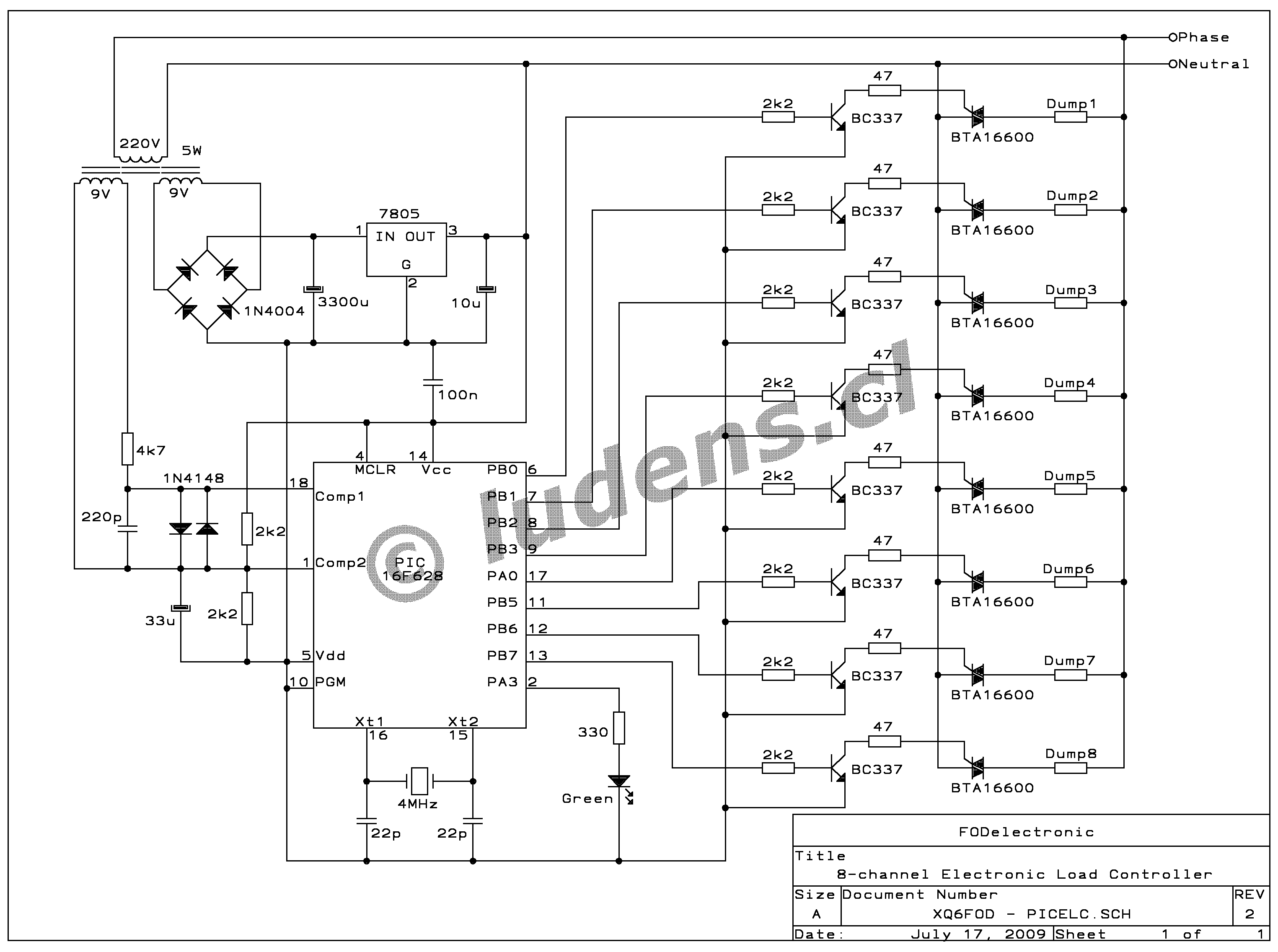
The TRIACs are directly driven, without galvanic insulation. To allow this, the 5 Volt Vcc for this
circuit is connected to the neutral side of the 220V line, allowing the PIC to pull
down the TRIACs' gates via small transistors that are able to conduct the
necessary trigger current. This negative triggering operates the TRIACs in quadrants where they have
high sensitivity, avoiding the fourth quadrant, which is usually harder to drive.
The lack of galvanic insulation makes the circuit simpler and saves some cost. Since the control is made on the neutral side, it is still safe to touch the control circuit while it's running, as long as the neutral is indeed properly grounded, but please don't touch it while it's connected, just in case if something is wrong with the grounding of your neutral line! The main disadvantage of not having galvanic insulation is that if a TRIAC blows, there is a chance that high voltage might blow through all the way to the PIC, and fry it. But since the PIC is much cheaper than the eight optocouplers that would be needed to insulate the circuit, I opted for the direct connection! It makes little sense to protect a component costing 3 dollars by using 20 dollars in additional parts! A TRIAC failure should be very rare, anyway. In the four months since I started using this ELC, I had two large thunderstorms, each of which produced nearby lightning hits that activated several ground fault interrupters in my house, and the ELC survived both. I think that proves adequate ruggedness!
This ELC triggers the TRIACs precisely at the zero crossings of the waveform. This is implemented in the software, so that no hardware measures are necessary to achieve this. The duration of the trigger pulse is also set in software, to one millisecond. That should be enough to get the TRIACs engaged even when the dump loads are very small, as would be the case when using the ELC with a low power turbogenerator.
While not shown in the schematic, of course each of the dump loads might (or even should, depending on the situation) have a circuit breaker between the phase line and the dump load.
The LED in the circuit is used to indicate that the generator and turbine are locked to the quartz crystal. If the LED does not light, it means the system is out of control, either because it's being overloaded by the user, or because the total dump load power is smaller than the excess generated power.
You can click the schematic to get a higher
resolution version.
The software for this ELC was written in PicBasic Pro. You can edit it with Notepad or any other text editor to make the changes you might need, then compile it with the mentioned compiler, and program it into the PIC using whatever PIC programmer you have or can build. I used the WinPic software together with a simple homemade programming interface. When you program the PIC, be sure to enable the normal external clock option, and also enable the low voltage programming, regardless of whether you use low or high voltage programming, so that the PIC will not try to use pin 10 as output (it's connected to Vss!). You need some working knowledge about PICs to do this. If you have never worked with PICs before, this project is a great way to start, and there are many web sites about the PIC microcontrollers, which will help you get started.
The program starts with the definitions of user variables for the phase period, and the integral and proportional gain. If you need 60Hz instead of 50, you have to change the period value. And depending on the electromechanical characteristics of your turbogenerator unit, you might need to change the I and P values to obtain stable operation combined with quick enough action. This might require a series of tests, each time removing and reprogramming the PIC, so be sure to mount it in a socket! I freely admit that this isn't very elegant, but this PIC doesn't have enough pins to easily add external controls to set the gains! In a future version, using a larger PIC, I will include such controls.
Then come pin definitions and the PIC setup variables, and then the program starts.
The program spends most of the time waiting for a zero crossing to occur. When that happens, the software goes immediately to the task that sends the proper trigger pulses to those TRIACs that were determined in the previous cycle to require being switched on now. After the pulses have been set, the software checks whether this zero crossing was upgoing or downgoing. In one case, it does nothing else and just goes waiting for the next crossing. In the other case, it processes the rest of the program. In this way, each of the eight channels is always controlled in full cycles, rather than in semicycles. This is necessary in order to keep the load on the generator balanced, with no DC component. When there is a DC component, typically there are slight saturation problems in generators and any transformers in the system, resulting in decreased efficiency, some audible noise, etc.
Note that whenever the analog comparator detects a zero crossing, the PIC will spend an entire millisecond applying the TRIAC trigger pulses. When it completes this task, the waveform has progressed quite a bit into the new semicycle. This completely avoids multiple triggering if the waveform should be noisy, avoiding the need for a Schmitt trigger. And having no Schmitt trigger, the zero crossing detection is highly accurate. This makes the trigger pulses start very precisely at the zero crossings, and last 1ms into the beginning semicycle, guaranteeing a clean, transient-free operation. For this reason, this ELC doesn't generate any radio interference through its TRIACs, unlike those ELCs that switch the TRIACs when voltage is present. For the same reason, no slope-softening inductors are needed for the TRIACs.
The abovementioned rest of the program consists of the following: The program will read out the PIC's timer, that was started one cycle ago, and then restart the timer to measure the present cycle. It will then compare the measured value to the nominal cycle duration, calculate the error, and apply a proportional-integral function to this error, to obtain a 15-bit value representing the required load. Since all this math is implemented in integer numbers, as PicBasic Pro doesn't have floating point math, more program space is devoted to the necessary limiting, than to the PI function proper! My implementation of this math is surely not the most clever possible, so if anyone can improve it, please do so, and send me the improved version!
The program then checks if the resulting value is within range, to enable the lock LED. If instead it's pegged, either high or low, the LED will be turned off.
All that follows from this point on is a routine that decides exactly which of the eight loads will be switched on during the next cycle. This will most likely require your modifications to suit your application, so I will explain the basics behind this:
I use this ELC in my house, and the eight dump loads are all useful loads: The kitchen is the biggest "client", with the range, the kettle, and the oven each using one ELC channel. Then comes the boiler that provides hot water to the house. Finally, I have four heating circuits connected to the ELC. The kitchen range takes 2.5kW max, the oven needs 1.2kW, the kettle and the boiler are 2kW each, and the heating circuits have each roughly 2kW of heaters connected, distributed all over the house. The range, kettle and oven are switched on and off as needed by the user (yours truly), the boiler is switched on and off by its internal thermostat, while the heaters are all left on all the time. The latter guarantees that the ELC always has enough dump load power connected, given that my microhydro system can deliver up to about 7kW.
To control all this, I decided to use a priority scheme: The range, which has no thermostat, but is manually switched to a wide range of power levels from zero to 2.5kW, gets priority one, so that I won't have to worry about my potatoes turning to coal because something else stopped using power. The oven gets priority two, since its own thermostat is able to compensate for varying degrees of momentary power availability. The kettle gets third priority, because it doesn't matter much if the water for my tea takes 3 minutes to boil, instead of just two. And the boiler gets fourth priority, because it's large enough that hot water for my well deserved shower will be available even if the boiler didn't get any power for hours.
Of course, all those loads that cannot accept interruptions or missing cycles, such as the lights, computer, music equipment, etc, which includes almost all outlets of the house, are directly connected to the generator, thus getting top priority, above the one gotten by any load connected to the ELC.
Any power left over, after powering the top priority loads and the four prioritized ELC-controlled loads, is available for heating. To obtain smooth, even, well distributed heating, I wrote the software to distribute this surplus power in a completely even way among the four heating channels. My house has good insulation and a very large thermal mass, so that the modulation of the heaters that results from other loads coming and going, cannot be felt at all. The thermal mass is even enough to iron out the variations caused by normal weather fluctuations lasting several days. And the summer/winter temperature variations are largely compensated for by the lower water availability in summer, so that the hydro system delivers less power. So the only thing I have to do to keep the temperature in my house constant to 1 degree, is to partially open some windows for more or less time per day, depending on the weather. However, since I'm a lazy guy, I plan to replace this ELC by a 12-channel version, adding four channels for dump loads outside the house, and adding a temperature sensor circuit, so that the ELC will double as thermal controller and keep the temperature in the house completely constant. I just need a PIC with more pins, which I didn't have on hand when I hacked together this ELC!
Back to the software: The 15 bit value, telling how much load power is needed, first is converted into the number of load channels that need to be on. For this, first the three most significant bits are stripped off and used. They can express anything from 0 to 7 channels. Then the remaining 12-bit value is added to a "fraction accumulator", which keeps increasing from cycle to cycle until it rolls over. When it rolls over, an additional channel is switched on, and when the addition completes without rollover, no channel is added. So, if for example the 15-bit number tells that five and one half channels need to be on, then this routine will alternately enable 5 and 6 channels on successive cycles. If the 15-bit number tells that 2.1 channels need to be on, then the result will be 9 cycles with two channels on, followed by one cycle with three channels on.
Then the program decides which of the eight channels have to be on. If the number of channels that have to be on is up to 4, then of course the channels are simply enabled in order of their priority. And when more than 4 channels need to be on, those exceeding this amount are the number of heater channels to be enabled. To achieve even distribution of power among the four heater channels, the software switches on channels in round robin fashion, remembering which of the four heating channels got switched on most recently, and starting with the following one the next cycle. So, if for example the software has calculated that 6.5 channels need to be on, then it will always keep the four priority channels on, and in addition it will switch on the following heater channels:
Cycle 1: Channels 5 and 6.
Cycle 2: Channels 7, 8 and 5.
Cycle 3: Channels 6 and 7.
Cycle 4: Channels 8, 5 and 6
And so on. So we have 2 or 3 heater channels enabled on alternate cycles, while each of the heater circuits gets the same on time, which is in this case 62.5% of the time, as evenly distributed as possible, given that only full cycles can be assigned.
You might want to modify this routine to get
more or fewer prioritized channels, up to making them all prioritized or all of
the same priority. It's entire up to you and your application.
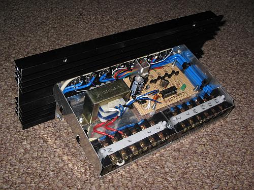
 I built this ELC using a piece of project board for
all the low power circuitry, and bolted the TRIACs to a generously sized extruded
aluminium heat sink. At the power level of my microhydro system, the heatsink
gets just barely warm. I needed the ELC as soon as possible, so
I didn't care much about a beautiful layout - I wanted it to work,
now
!
I built this ELC using a piece of project board for
all the low power circuitry, and bolted the TRIACs to a generously sized extruded
aluminium heat sink. At the power level of my microhydro system, the heatsink
gets just barely warm. I needed the ELC as soon as possible, so
I didn't care much about a beautiful layout - I wanted it to work,
now
!
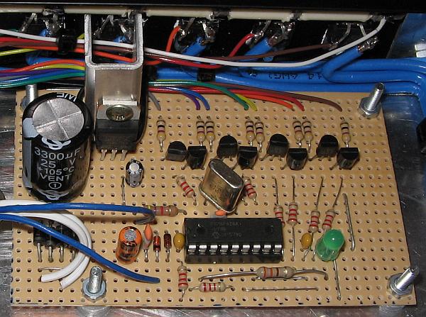
The PIC was installed in a socket, so that it can be easily removed, to change parameters in it, or even to make radical software changes.
The voltage regulator was bolted to an U-shaped junk-box heatsink, which is also larger than necessary. Actually, the regulator could probably work without any heatsink in this circuit, but it's safer to use one. After all, heat is the biggest enemy of electronic components.
The copper pattern of the board is just like a protoboard, that is, a few long copper strips for power distribution, and many short transversal strips between them. It's very convenient for most uses, but here I had to bend the pins of the crystal to make it fit without needing jumpers.
This little board, the transformer, and the
connection blocks, were mouted on a simple homemade aluminium sheet chassis,
which was bolted to the heat sink. You have already seen the photo of the
completed ELC, at the start of this page. Despite the use of the project board
instead of a real PCB, the assembly is solid and dependable.
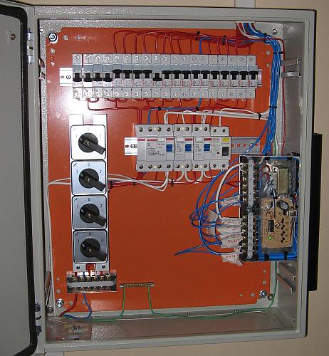 I installed this ELC in my house's
main distribution box. Here you can see the distribution box,
still half-ready, but working fine. It's a somewhat complex circuit, compared to most home
distribution panels, because it includes switches for selective enabling of
dual backup systems (gasoline powered generator, and battery/inverter); it
is 220V for the most part, but includes a 110V circuit for some outlets
in the house, and the controlled loads are switchable between 220 and 110V,
to adapt them to my small 1kW summertime turbogenerator, when necessary. There are
ground fault interrupters for everything, four separate ones, with the one for
the ELC and its loads being a four-circuit unit. These are normally used in
three-phase systems, but here I need the four channels to pass 220V, 110V, a voltage-switched
phase, and the neutral.
I installed this ELC in my house's
main distribution box. Here you can see the distribution box,
still half-ready, but working fine. It's a somewhat complex circuit, compared to most home
distribution panels, because it includes switches for selective enabling of
dual backup systems (gasoline powered generator, and battery/inverter); it
is 220V for the most part, but includes a 110V circuit for some outlets
in the house, and the controlled loads are switchable between 220 and 110V,
to adapt them to my small 1kW summertime turbogenerator, when necessary. There are
ground fault interrupters for everything, four separate ones, with the one for
the ELC and its loads being a four-circuit unit. These are normally used in
three-phase systems, but here I need the four channels to pass 220V, 110V, a voltage-switched
phase, and the neutral.
There are still a few switches and connections missing. But at the top left, there are four spare circuit breakers, which are intended for the external dump loads, when I build that 12-channel thermal control version of the ELC.
When all that has been done, I also
intend to tidy up the wiring, replace the masking tape cable IDs by more elegant
ones, and make a panel to hide the mess! Also some meters would be nice to have.
For the moment, the only indicator is the ELC's LED, which is glowing in this
photo, indicating that the system is working correctly and I'm getting accurate
50Hz.
Back in the age of our grandfathers, microhydro systems were implemented without an ELC. Typically these systems had a mechanical or hydraulic speed governor, which in some cases controlled the water supply via a spear valve or similar device, or it acted upon a deflector that moved the jet away from the turbine, and some systems even had the speed governor act on a mechanical brake. In any case, this resulted in a reasonably constant speed (and thus frequency), and the voltage was set by manually adjusting a rheostat controlling the generator field current. Often the load current was coupled back to the field, which resulted in increasing the field current when there was more load, so that the output voltage was pretty constant.
These systems usually worked quite well, but they had their problems. First of them was that they reacted slowly. Slowest of all was the one that controlled the water valve, because it had to be slow, in order to avoid water hammer effects in the penstock! The others could be faster, but were still limited by the inherent limitations of mechanical systems. To make up for the slow response of the mechanical speed governors, large, very heavy flywheels were used to stabilize the speed by brute force.
Another problem was, of course, maintenance and wear. Mechanical systems need to be lubricated, cleaned, adjusted, and even then they break down rather easily. Specially the mechanical brake system produced a lot of friction, heat and wear. Add to this an assortment of problems like the tendency of spear valves to clog with small debris, and the tremendous spray in the turbine housing when a deflector is used.
Also, the lack of real voltage regulation made it hard to use some of these systems with sensitive loads.
The massification of electronic devices made it possible to radically change the approach. It soon became standard practice to provide generators with built-in, highly accurate and reliable electronic voltage regulators, usually called "AVR" (automatic voltage regulator, to differentiate it from the old manual field current adjustment!) by the generator manufacturers. At that time, microhydro builders became interested in using electronic speed control too, that works without any mechanical actuators.
The basic concept any ELC uses is to let the turbine and generator run at their full power, or possibly a manually set partial power, and keep the electric load just right to attain the correct speed. It's very similar to the old mechanical speed governor that acts on a mechanical brake, only that an ELC uses electrical braking: Dump loads into which excess electric power can be put.
So an ELC will measure turbine speed, and control the power delivered to one or more dump loads, to keep the speed correct.
To measure the turbine speed, there are several methods. When the generator is of the synchronous type, it's easiest to simply measure the frequency produced by the generator. If instead an induction motor is pressed into generator service, it won't have internal voltage regulation, so it's better to use the ELC as a voltage regulator, and sense voltage rather than frequency. This will only produce a rough speed control, but that's better than having equipment burn out from unstable voltage! And finally, a dedicated tachometer could be used, but I don't think anyone does this in the microhydro world.
The power devices used to control the dump loads can be relays (very poor choice), thyristors (TRIACs for low and moderate power, antiparallel SCRs for high power), MOSFETs, or IGBTs. With relays, only very basic slow on/off control can be done, resulting in unstable speed, and the relays tend to wear out quickly. With thyristors, four types of operation are possible: Simple slow on/off (slower than the line frequency), individual half cycle control, individual full cycle control, and phase control within each half cycle. In principle thyristors can also be used for more sophisticated control, using additional thyristors to turn off the main ones before a half cycle is over, but that's rarely done nowadays. Finally, with MOSFETs or IGBTs it is possible to implemente any of the control methods mentioned, plus high frequency pulse width modulated control. IGBTs have a better power handling to price ratio, while MOSFETs can work at higher frequency, reducing the size of filter components.
Each control method has advantages and problems. Simple non-synchronous on/off control is very easy to implement, for example using LED-meter ICs, but the performance in terms of speed control is poor, and it causes switching spikes and corresponding slight radio interference. By using zero crossing trigger circuits, the spikes and interference can be eliminated but the other disadvantages remain. When instead controlling individual half cycles, speed control is improved, there is no interference, but in many operating conditions the load to the generator will be asymmetric, that is, will have a DC component on it. In some cases this causes trouble, in other cases it doesn't. I used an experimental ELC with half cycle control for some months, with no problems to my generator, but with my transmission transformers producing some odd noise from flux shifting and the resulting slight saturation. Full cycle control eliminates this problem, but is only half as fast as half cycle control, so the speed control is less good. Phase control at the line frequency achieves very good speed control, but has serious interference and waveform distortion issues, because of the inevitable inductance of the generator's windings: Whenever one of the control elements fires in the middle of a half cycle, the additional load current combined with the generator's inductance will make the voltage break down sharply, and then take typically around one millisecond to recover. This generates some heavy radio interference, which is important if the generator and/or ELC is close to the place where the power will be used, and it also tends to make any motors, transformers, and some other devices produce pretty loud noises from the high harmonic contents of the waveform!
In addition, all these methods cause a constantly changing load on the generator. The changes might happen slowly or fast, but always happen, and that translates into a poor power factor, requiring the generator to be oversized. When many dump loads are used, the extent of this problem is small, but it is a very bad idea to use such control with a single dump load.
Instead, when high frequency (many times the line frequency) pulse width modulation is used, along with proper filtering, this problem disappears. Such PWM control can have unity power factor, very smooth speed control, and can work with a single dump load, but it's more expensive to implement, and also larger and much heavier, because of the filtering required. And that filtering is mandatory, because otherwise a PWM ELC generates a terrible amount of radio interference! Actually it can be hard to make the filter good enough to reduce interference to an acceptable level. The losses, and thus the heat production, are also larger than when using low frequency control with thyristors, because the MOSFETs or IGBTs normally need to be combined with several diodes, which cause additional loss, and the switching loss at high frequency is significant too. This further adds to size, weight and cost, because of the larger heatsink required.
So, each system has its weak points and its
strengths. You can buy ELCs using any of these different systems, from several
manufacturers, but some are of poor quality, many are very expensive, and a
few are both! The problem is that microhydro is a niche market, and ELCs are
typically hand-made in very small quantities. This necessarily results in an
unfavorable ratio of cost to performance. So ELCs belong to the select group of
electronic projects which really make a lot of sense to build at home!
When I implemented my microhydro system, I first built a slightly modified version of Jan Portegijs' Humming Bird ELC, which is a TRIAC-based phase control ELC that also includes user load protection against abnormal operating conditions. For nearly a year this was the only ELC I used. It works very well, produces a very good speed control, no light flickering (most of the time), but because of its operating principle it distorts the waveform and generates some RF interference. The interference was no big problem for me, despite being a radio amateur, because the turbine and controller are located far enough from the home. But the waveform distortion caused acoustic noise in some devices, pretty strong in a few of them. Also, the waveform distortion at some specific trigger angles interacted with the generator's voltage regulator, so that at these specific conditions suddenly the whole system became slightly unstable and the lights would flicker!
Then I added the ELC described on this page. My present setup is that the Humming Bird remains at the turbine site, but is adjusted to 52Hz instead of 50. And at the home I have my new full-cycle ELC, which regulates to precisely 50Hz. The effect of this is that normally the new ELC is controlling the turbine, and distributing the power in my home at the same time, while the Humming Bird just sits there, sending no power to its dump loads. If for any reason the transmission line to the house opens, the circuit breakers come down, or whatever, then the Humming Bird steps in as a sort of emergency regulator, limiting the frequency to a very safe 52Hz, equivalent to a rotational speed of 1560 rpm. Also, the protection circuits of the Humming Bird remain active at all times, so that I don't need any additional protection systems in my new ELC.
How does the new ELC perform, you surely want to know! It basically does its job quite well, the frequency accuracy is very good of course, but its reaction speed is inevitably slower than that of the Humming Bird, because its basic control bandwidth is only half as wide, a direct result of using full cycle control. This results in the turbogenerator making small speed excursions, lasting about one half second, when a big load is switched on or off. However that's no problem in practice. All interference is gone, and the strange noises in transformers and motors are gone too. And there are no spikes to cause interaction with the generator's voltage regulator.
But there is STILL some sort of light flickering! The problem is this: Like described above, all non-PWM ELCs place a variable load on the generator, as the dump loads come on and off. The voltage regulator in my generator is designed to keep the peak voltage of the waveform constant, and it does this very well indeed. But the waveform the generator delivers changes significantly with load! It's sort of a sine wave, but getting more slender or wider depending on load. So the peak to RMS ratio varies with load, and since the regulator keeps the peak constant, the RMS varies all the time! Glow bulbs react to the RMS voltage, so any glow lamp now flickers all the time, while with the Humming Bird it only flickers at very specific levels of power delivered to the dump loads. Compact fluorescent lamps instead react mostly to the peak voltage, thanks to the built-in filter capacitors behind their input rectifiers, and for this reason they do not flicker at all now! So I'm happy, because the only glow bulb in the whole house is the little one inside the fridge, while all my other lights use compact fluorescent lamps. So far, so good, I can live with a flickering fridge light!
This experience makes it clear that the only really good, do-it-all, high quality, guaranteed flicker-free option is a fully fledged high frequency PWM ELC with extensive filtering. When I first planned my microhydro system, I intended to build one. Then, due to work overload from all the other stuff I had to do, I postponed this lenghty work. I still intend to build the definitive PWM ELC some day, but until then, the ELC described on this page, together with the Humming Bird as a backup, are serving me very well.
If you now have any patience left to keep reading web pages, you might want to read about the microhydro installation for which I built this ELC!
Back to homo ludens electronicus.