Power inductor tester
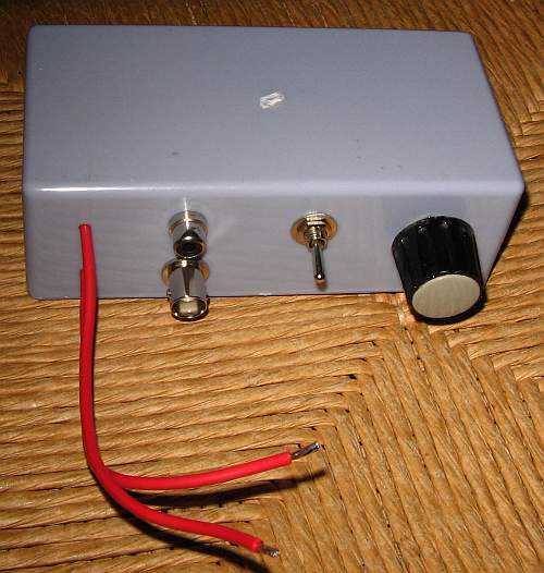
When building or repairing switching power supplies of all sorts, and
also in many other situations, it's essential to be able to test and
measure inductors and transformers. While there are some inductance
meters available cheaply enough, they tell only part of what one needs
to know, because they usually are unable to test an inductor for
saturation current, let alone determine its linearity.
For that reason I built a simple gadget that in combination with a lab
power supply and an oscilloscope will allow measuring
inductance, see
the magnetization curve of an inductor, find out saturation current,
how sharp the
saturation is, and see whether the inductor actually saturates, or is
current-limited by resistance.
Magnetic components such as inductors and transformers are the least
understood by most people doing electronics. So this little gadget also
has a considerable educational value!
I built the first inductor tester of this type more than 20 years ago.
That version never got a housing! It lived naked, free and healthy, all
components in
clear air. Then, about ten years ago, I built a more modesty-endowed
one into a little plastic
box. That's the version I'm finally publishing here!
This circuit can test inductors over the whole range of inductances
usually seen in switching power supplies, inverters, chargers, motor
controllers and the like, and it is capable of testing the saturation
current up to about 100A.
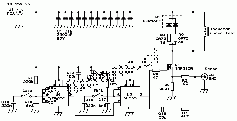
As you can see, the circuit is very simple. There is a big bank of
capacitors, a timer circuit using two 555 ICs that generates a train of
variable length pulses, driving a MOSFET that applies these pulses to
the inductor under test. The inductor current is sensed by a low value
resistor, the resulting voltage being applied to an
oscilloscope,
where the measurements are made.
The first of the 555 chips generates the repetition rate of the pulses,
while the second 555 generates the actual pulse length applied to the
inductor. There is a range switch, which selects the timing capacitors
for both timers, and a potentiometer that fine-adjusts pulse length. In
the slow range, the repetition rate is roughly 20Hz, which is about the
slowest that allows getting a stable, easily readable trace on a
typical scope. The pulse length is adjustable from
roughly 300µs
to 10ms in this range. In the fast range the pulse length goes from
10µs to those
300µs, and the repetition rate is roughly 600Hz, which
gives a good trace intensity at the sweep rates used for those pulse
lengths. So, this circuit basically covers the pulse length range of
10µs to 10ms, with appropriate repetition rates.
The output of the second 555 directly drives a high current MOSFET,
which connects the capacitor bank to the inductor under test. The
capacitors are conveniently charged to slightly over 10V from a current
limited lab supply, so that the voltage applied to the inductor is as
close as possible to 10V. This simplifies further calculations. But any
supply voltage from 10 to 15V can be used.
The current sense resistor is 10mΩ, so that the output to the scope has
a scale of 10 millivolt per ampere. A very narrow sample of
the
drive pulse is also coupled to the scope output through C18 and R7, to
facilitate scope triggering at the start of each pulse.
Finally, there is a diode/resistor circuit to safely discharge the
inductor after each pulse finishes, instead of frying the MOSFET!
Click on the schematic if you want a larger, better resolution version.
And fix the MOSFET number, it's really an IRF3205, not 3105! It seems I
misplaced the original schematic file, so I can't fix it
myself...
I used a 3105 at first, but later changed it to a 3205, which has much
lower resistance.

I built the circuit on two pieces of perfboard. One holds the power
circuit, prominently including the collection of electrolytic
capacitors. I didn't buy these, but instead raided my
collection of
junked electronic boards, and robbed every 3300µF capacitor I
found! When you build your version, of course feel free to use any
large capacitors you happen to have. The goal is to get roughly
40,000µF or more, along with a very low ESR. A voltage rating of 16V is
actually enough, and any more won't hurt.
The MOSFET and power diode don't neet heatsinks, thanks to the low duty
cycle they work at.
The control circuit was assembled on a separate board, both for
practical reasons, and to prevent magnetic interference from the high
pulse current into the timer's high impedance areas. The range switch
was mounted on this board, so that the whole board can be conveniently
supported just by that switch.
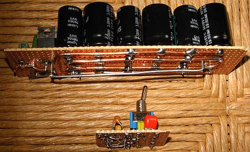
This peek allows you to see the thick wires used to interconnect the
capacitors, MOSFET, diode and power resistors. We want low ESR, right?
If you look carefully, you will notice that most wires are copper, but
there is one shiny silvery wire. That's the 10mΩ resistor! It's a plain
and simple piece of galvanized steel fencing wire! I think the gauge
was AWG #16. Its temperature coefficient might not be the best, but
it's cheap, available, easy to solder, and works well enough! I often
use galvanized steel wire to make such low value power resistors.

And here you can see how the boards and other stuff fit in the little
plastic project box - just barely.
I used a BNC connector for the scope output, and an RCA connector for
the power supply input. Instead the connections to the inductor under
test have no connectors at all. Instead I used thick, short stranded
wires, which I tack-solder to the inductors. That's a lot better than
using any clip connectors, when we want to push 100A pulses through
them, and don't want much resistance!
So much for the construction of this gadget. Now let's go on to using
it!
The inductor tester must be powered by a current-limited power
supply, because otherwise it would be easy to far exceed the power
dissipation capabilities of the discharge resistors, when setting the
controls to a pulse length too long for a given inductor. The power
supply should ideally be adjustable to slightly more than 10V, say,
about 10.2V for low current inductors, and up to 12V for the
biggest ones. If such a supply isn't available, a fixed 12V will do,
but then you will probably need a calculator instead of just your head,
when doing the math.
The current capability of the supply should be about 1A. That will
suffice for almost all tests you will want to do. But if you run out of
juice when testing a very large inductor, you might want to increase
the current limit to 2A or even 3A, but then do only very brief tests,
or you will melt down the tester! On the other extreme of things, when
you test tiny coils and transformers, this gadget can easily deliver
enough current to vaporize thin wires and completely melt down
small coils, so you really should use a lab supply that has a
current limit adjustable down to a low value. I like to use a 100mA
limit when testing small components, and even that can be too much for
the smallest ones!
The idea, in any case, is that if you set a pulse time that's too long,
the power supply should go into current limit well before your inductor
under test gets damaged, or the tester itself lets out its magic smoke!
The scope needs to have a calibrated scale, DC response, and be able to
trigger on the positive edge. Essentially every scope, except absolute
antiques from the time of WW2 and before, meets these requirements.
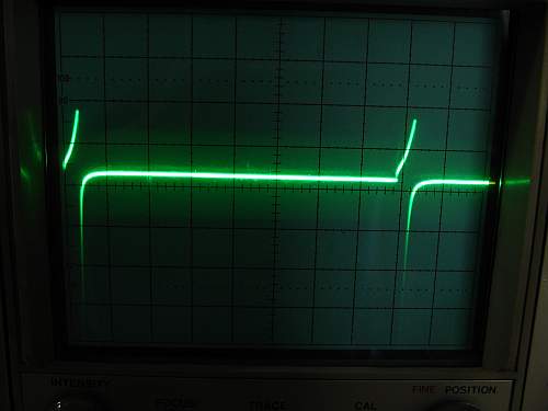
This is the complete waveform displayed on the scope. It begins with a
positive ramp, as the current in the coil increases while the circuit
applies 10V to it. Typically this ramp will not be linear - it can have
one, two or even more bends in it, caused by saturation and other
nonlinear effects of the core, by the winding resistance, and
even
by the tester.
Then the ramp ends, which results in a negative pulse coming
both from the drive circuit and MOSFET capacitances. Note that this
isn't the inductive discharge of the coil! That one is routed away from
the scope. Although some of the inductor discharge current might be
magnetically coupling to the scope output.
And then comes a rest time, after which the cycle repeats. If you look
very carefully, you can see the positive trigger pulse at the start of
the second ramp. The one at the first ramp is hidden by the first grid
line!
You should start testing an inductor by connecting the inductor
(soldering it), setting the tester to the shortest pulse length, then
switching on the power, adjusting the scope to see at least the full
first ramp and some area around, and then slowly increase the pulse
length until you see the ramp bending upwards. This is the saturation
point of the inductor, and it usually makes little sense to test at any
higher current. Don't crank up the pulse length much further, or you
will get really large current pulses, and possibly some smoke.
What you have to do now is adjust the scope to see the interesting part
of the curve in good detail. That's the entire ramp until the
saturation point, in most cases.
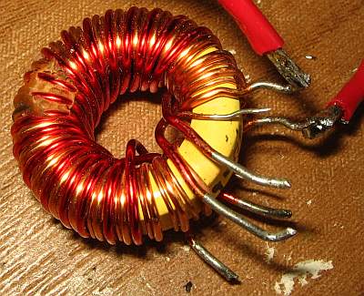
Let's start with this animal. It's the filter choke of a multivoltage
half bridge forward converter, a.k.a. PC power supply. It's wound on a
toroidal core made from very dense, fine grained, powdered iron. These
cores have a permeability of around 70 to 100, which is the highest
available from powdered iron.
For the test, I connected only one of its windings. I think it's the
12V winding. The other windings were left open.
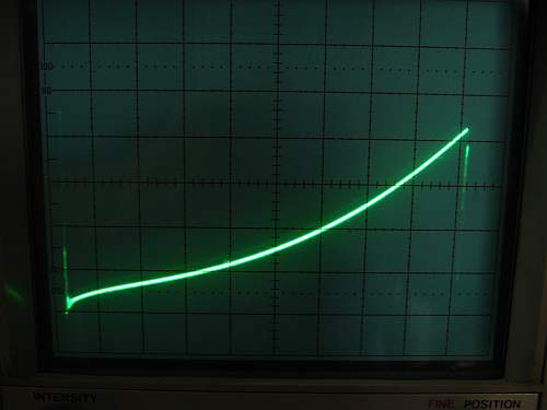
This is the ramp I got. The scope is set for 100mV and 10µs per
division. What we can see is that after some ringing where the ramp
starts, given by stray capacitance, the ramp starts at a certain angle,
then after about 5µs gets slightly less steep (meaning the inductance
increased at that current level!), and then after about
30µs the trace gets steeper again (inductance is reducing at
that
current level). This reduction of inductance continues, and is known as
the saturation knee. Eventually the trace gets straight again, much
steeper than at the beginning. It's here where the core is completely
saturated, and we have basically the same inductance left as if the
winding had been made on thin air instead of an iron core.
The saturation of this core is very soft, indicated by the soft knee,
having a large radius, compared to the size of the whole ramp.
Zero voltage is at the line one division up from the bottom. If we
take as saturation limit the middle of the knee, which is
roughly 50µs after the beginning of the ramp, this is a
voltage of
150mV. Considering that the inductor tester has a 10mΩ sensing
resistor, this means a coil current of 15A. So we can say that this
inductor saturates very roughly at 15 amperes flowing in its 12V
winding. By counting the number of turns and multiplying that by this
current, we can arrive at a certain amount of ampereturns that
will saturate this particular core, but we have to keep in mind that
with the saturation of this core being so soft, it's hard to
say
at which level we will consider it to be saturated!
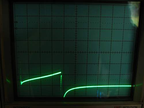
To measure the inductance of this winding, the scope settings above are
not good enough. The inductance we usually want to measure is
the amount before saturation, and that part of the trace is too small
to allow precisely reading the screen.
So, first we reduce the pulse length, to finish the pulse
before
the core saturates. The scope settings in this shot are still the same,
just the pulse length was reduced.
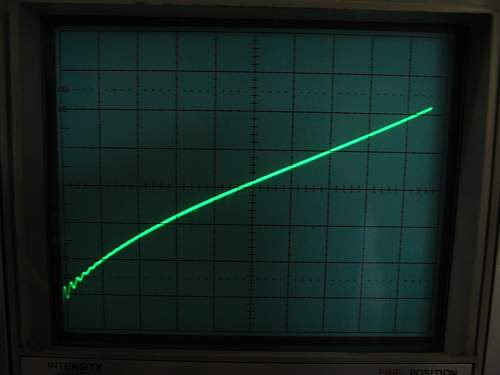
And then we readjust the scope to make good use of the screen. In this
case the settings are 10mV and 2µs per division.
The inductance that's most meaningful in power electronics is the one
at medium currents, well before saturation, but not at very low
current. Anyway this simple inductor tester has some parasitic effects
at the very start of the pulse, given by the gate charge pulse of the
MOSFET, so it's better to avoid that area. So I will take the last 5
horizontal divisions of this trace, where it is a nice straight ramp.
This is 10µs, and 2.2 vertical divisions, which is 22mV, representing
2.2A. So we know that with 10V applied, this inductor lets the current
grow by 2.2A in 10µs. And now we can apply the definition of the Henry:
H = V × s ÷ A
Inserting our values,
10V × 0.00001s ÷ 2.2A = 0.000045H
So the inductance is 45µH.
Since it's easy enough to count the number of turns of this winding, we
can now calculate both the AL value and the saturation ampereturns for
this core, and those are the main bits of data needed to design any
coil using it! Just the core loss is a separate entity that this tester
does not measure easily. Still, you can take any unknown core, wind a
test coil on it, and use this tester to determine the core's main
characteristics. That's a very useful thing to do!
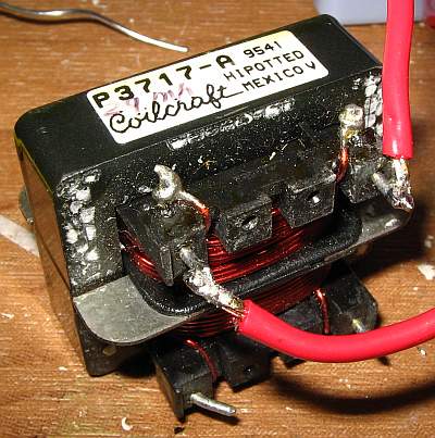
Let's try another guinea pig. This slightly injured but still perfectly
functional thing is a common mode choke, intended to be used in noise
filters at the input of switching power supplies. They are usually
wound on high permeability ferrite, which has a strong resistive
(lossy) component in the RF range, producing good absorption of
unwanted RF signals.
Like in the case above, I connected just one winding.
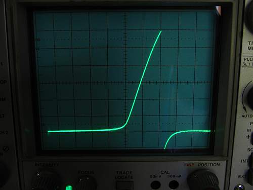
This shot was made at 20mV and 100µs per division. The very sharp, well
defined saturation knee is immediately obvious. Before the knee, the
ramp has a very low slope, indicating a high inductance. After the
knee, the inductance is very much lower.
Just for fun, let's calculate how much inductance there is, when the
core is saturated:
In 5 vertical divisions we get 1.8 horizontal ones. That's 100mV,
meaning 10A,
in 180µs. The applied voltage is of course 10V, defined by the lab
power supply. So:
10V × 0.00018s ÷ 10A = 0.00018H, or 180µH.
Remember that this is the inductance when the core is saturated!
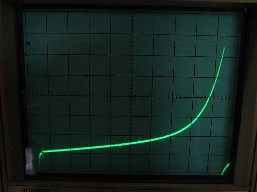
Now I have reduced the pulse length to include the saturation knee but
stop after it, and I have reset the scope to 1mV and
50µs
per division. We can see that significant saturation starts at
1
division up from the zero line (0.1A), the knee is centered roughly on
1.6 divisions (0.16A), and the core is totally saturated at roughly
0.4A in this coil.
Over the usable part of the ramp, before saturation, we get about 0.6
vertical divisions in 5 horizontal ones. That means 0.06A in 250µs,
which results in roughly 42mH. Note this is millihenry,
while all inductances mentioned above were much smaller, and indicated
in microhenry!
So, we can say that a single winding of this common mode choke has an
inductance of 42mH, has hard saturation at roughly 160mA, and when
saturated it has 180µH left - which means that the inductance
drops
by a factor of 233 due to saturation!
This behavior is typical of inductors wound on high permeability
ferrite cores, without air gaps. In fact the sharp saturation of this
choke is an indication that the residual airgap, which results from
imperfectly polished mating surfaces of the core halves, is very small,
indicating good quality of the core finish.
Just to prevent risking any wrong conclusions on the side of my
readers: The normal way a common mode choke is used consists of
connecting its two windings in series with the two poles of the power
line. So, all the big current flows through the two windings in
opposite senses, canceling the magnetic flux. For this reason this
common mode choke can take several amperes in its normal operation
mode, without getting even close to saturation. The actual working
current is limited by heating of the wire, and not by the
core!
Also the choke will oppose almost no inductance to such normal mode
(differential mode) currents. But it will oppose its full non-saturated
inductance to low frequency common mode signals, and at RF it will be
lossy, absorbing RF noise.
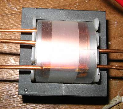
Here we have our next guinea pig: A homemade tape-wound transformer
intended for a 12V to 220V inverter. It has a 2×12V primary and a 45V
secondary. Several push pull converter blocks, each using one
of these
transformers, are connected with their secondaries all in series.
For
this test, I used the secondary winding.
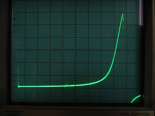
The trace resembles that of the common mode choke. After all, both use
high permeability, ungapped ferrite cores! But one difference is
obvious: The knee is softer. This is due mainly to this low cost core
having less well polished seating surfaces, so that there is a
significant, irregular air gap. As a result, granules of ferrite
actually touching at the joint of the core halves will take lots of
flux, and saturate first, while those granules separated by some air
will only then start taking more flux, and saturate a little later. The
whole core will saturate well after that. This spreads the saturation
phenomenom over a wider current range, extending and softening
the
knee.
Another difference is less obvious: The ratio of the
inductances
in saturated and non-saturated conditions is a little less extreme than
for the common mode choke. This is because the ferrite used for this
transformer has a slightly lower permeability.
And of course the absolute values of inductance and saturation current
are different, due to totally different turn numbers and core
dimensions.
The inductance measured in a transformer like this defines the
magnetizing current it will take, when a certain voltage and frequency
are applied. This magnetizing current needs to be kept below the
saturation level, and at any frequency above roughly 10kHz it needs to
be kept even lower, in order to avoid excessive core loss and heating.
The actual current carried by each winding can be very much larger,
because the primary and secondary currents cancel out, except for that
magnetizing current.
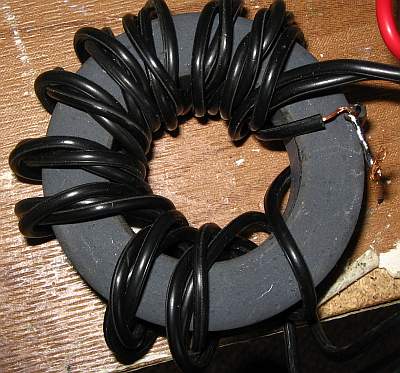
Let's take this last test coil, to illustrate a few more points. This
is an FT-240-61 toroid, made from low permeability ferite, wound with a
quick and dirty trifiliar winding that I used to generate a balanced
signal for an equally quick and dirty test, some time ago. Now I pulled
it out of my
junk box, and connected the three wires in series. This stranded wire
is quite thin, so it has a significant resistance at high currents.
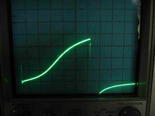
This is the curve it gives. It's nice, because it allows us to see a
pretty linear ramp at the beginning, then a moderately soft saturation
knee, then a steeper ramp in the saturation area, and then a roll-off
toward a horizontal line. This last bend is caused by the wire
resistance. The scope was set for 200mV per division, meaning 20A per
division, so the trace ends at a current of roughly 72A, at which the
thin stranded wire is seriously limiting the current due to its
resistance. It looks like the curve would level off at roughly
80A. Knowing that there are 10V applied, this means that the total
resistance of the winding is 0.125Ω, which seems quite reasonable for
the length and size of wire used. Which shows that my little gadget can
even measure coil resistance, in a more fancy way than using a
multimeter!
Note that the saturated and unsaturated inductances are far less
different than in the other ferrite cores above. That's because of the
low
permeability of this ferrite, barely a bit higher than that of the
powdered iron core at the beginning!
There is no need to worry that this crooked curve could distort the RF
signals, when using this core for a high power balun, as is often done.
Due to the high core losses at RF, all signals are kept to very low
flux levels,
so low that they would be hidden in the blurry spot at the very
beginning of this trace! At that low flux level, the balun is
completely linear, for all practical purposes.
Audio transformers instead, which often use quite high flux densities,
do
suffer from distortion introduced by core nonlinearity. The
core
magnetizing curve directly affects the magnetizing current, and through
several effects this impacts the signals in an audio transformer.
That's the main reason why HiFi sound reproduction became so much
better when tubes, with their almost inevitable transformers, were put
in the museum, and replaced by transformerless solid state circuits.
Tube audio fans will of course tell you the opposite story, in the line
that tube equipment sounds better, because
of the transformer and triode distortions! What sounds more enjoyable,
the clean audio or the distorted one, is a matter of taste...
But that transformerless equipment has less distortion, is an
easily measurable and
audible fact.
Well, enough playing for now. If you want to keep playing and testing
inductors, learning how they work, build your inductor tester and use
it!
Back to homo ludens
electronicus.


