Designing and building
Conical Horn Antennas
The coaxial-cable-fed conical horn antenna is a good option when an
easily built, moderate gain, linear polarization antenna is required
for a higher UHF or lower microwave band. It can only handle a
moderate bandwidth, but it's reasonably uncritical to build, and can be
made from widely available, cheap or even free materials. It's larger
than a Yagi antenna of the same gain, but far less critical to build,
and so it can be built and used without needing calibration.
There are lots of conical horn antenna designs published on the web and
elsewhere, mostly for the 2.4 GHz WiFi band, but when I recently needed
to build
some antennas for the 2600 MHz LTE band, I couldn't find a
single
place that offered all necessary design equations. Instead I found them
in various different places, websites and books, disguised in various
ways. So I thought it might be useful for fellow antenna builders to
place everything on a single page. For this purpose I worked out
straightforward design equations that the practical antenna builder
will probably find useful.
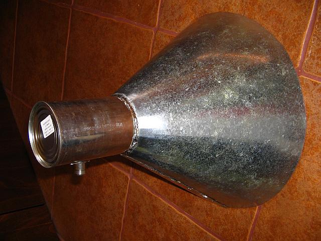 The
antenna consists of two fundamental sections: A coaxial to cylindrical
waveguide transition, and the horn antenna proper, which is
simply
a funnel made from sheet metal.
The
antenna consists of two fundamental sections: A coaxial to cylindrical
waveguide transition, and the horn antenna proper, which is
simply
a funnel made from sheet metal.
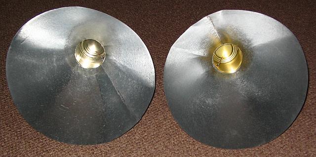
The waveguide is often made from a tin can, as shown in this photo. If
no suitably sized can is available, it can be made from sheet metal.
The horn is almost always made from sheet metal, although in
some lucky cases one might find a metal funnel in just the right size.
A good kind of metal sheet could be copper flashing, but for reasons of
cost and availability I like to use zinc-plated steel sheet of 0.3mm
thickness, which is widely available and inexpensive. Tin-plated steel
sheet is better, because it can be soldered more easily, but it tends
to be less available. Avoid zinc-aluminium-plated steel, because it
can't be soldered. Aluminium sheet is of course unsuitable for the same
reason.
The seams require continuous conductivity, so they should be soldered
all along. Making the seams with rows of screws or rivets isn't
satisfactory, unless they are placed very close together, almost
touching each other.
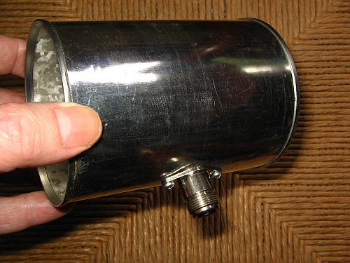 The
coaxial to waveguide transition is simply a cylindrical can with one
closed end, having a coaxial connector installed at a strategic
distance from the closed end, and this coaxial connector carrying a
short probe.
The
coaxial to waveguide transition is simply a cylindrical can with one
closed end, having a coaxial connector installed at a strategic
distance from the closed end, and this coaxial connector carrying a
short probe.
For a given range of frequencies the builder can freely select the
diameter of the waveguide, within certain limits, and he can also
select the desired mouth diameter of the horn, which will basically define the gain
of the antenna. Once these decisions have been made, the other
dimensions are calculated. These are mainly the distance between the
closed end of the waveguide and the probe, the length of this probe,
and the angle of the cone.
The choice of connector is up to the builder. Type N connectors are a
good choice when the antenna will be fed with "large" coax cable, such
as RG-8, RG-213, Belden 9913, LMR-400, with a BNC connector being a
good choice if "small" cables will be used, such as RG-58, and SMA
connectors being the best choice when "miniature" coax cable is used,
such as RG-174 or RG-316. However it should be noted that at
frequencies where it makes sense to use horn antennas, the losses of
coax cable are high, and for any significant length a large, low loss
cable should be used. Otherwise the loss in the cable can easily offset
the gain of the antenna!
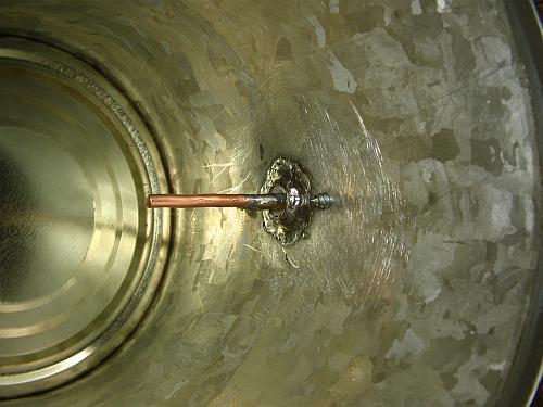 Here
you can see the inside of the coaxial to waveguide transition. The
probe is made from heavy copper wire. The critical dimensions are the
distance between the axis of the probe and the bottom of the tin can,
and the length of the probe, measured from the end of the connector's
external conductor. The connector is mounted to the tin can with two
sheet metal screws, and then its external conductor is soldered to the
can.
Here
you can see the inside of the coaxial to waveguide transition. The
probe is made from heavy copper wire. The critical dimensions are the
distance between the axis of the probe and the bottom of the tin can,
and the length of the probe, measured from the end of the connector's
external conductor. The connector is mounted to the tin can with two
sheet metal screws, and then its external conductor is soldered to the
can.
Now lets start the equations to design the coax to waveguide
transition. All dimensions are in millimeters, and all frequencies are
in gigahertz.
The absolute minimum inner diameter required is:
Dmin = 171 ÷ Fmin
where Fmin is the lowest frequency of operation, and Dmin is the
minimal inner diameter.
But it's undesirable to use a diameter as small as this, because it
requires an excessive length of the waveguide. A better value to use
for the minimum internal diameter is roughly:
Dmin = 190 ÷ Fmin
And the largest diameter that can be used is:
Dmax = 230 ÷ Fmax
where Fmax is of course the highest frequency on which the antenna will
be used.
You can see that a waveguide of a given diameter will work optimally
only over a frequency range of 1:1.21. You can stretch this a little by
selecting a diameter strictly by the last equation, according to the
highest frequency to be used, and let the lower part of your band
extend into the range where performance suffers. Still the absolute
maximum practically usable bandwidth is less than 30%. However this is
enough for many applications.
If your bandwidth requirements are less than 20%, you can freely select
the
diameter from within a range. For best performance it's
advised to
use the largest possible diameter that is clearly smaller than the
limit given
by the third equation. Doing so will minimize the detuning
over
the band.
Once you have decided what diameter to use, typically by checking your
kitchen or a supermarket for the best-suited tin can, you can calculate
the other dimensions. The distance between the bottom of the tin can
and the center line of the probe is given by:
Dprobe = 75 ÷ ( F × √( 1
- ( 30923 ÷ ( F² × D² ))))
where D is the actual inner diameter of the waveguide and F is the
center frequency of your desired band. Maybe some algebra wizard among my readers can further simplify this equation.
The length of the probe, measured from the end of the external
conductor to the tip of the probe, is:
Lprobe = 71 ÷ F
assuming that the length to diameter ratio of the probe is
roughly
as the one shown in the photo above, that is, it's a rather fat probe.
If the wire instead is very thin, the correct length is more like
Lprobe = 73 ÷ F
But then its bandwidth would be poor, so it's best to use a fat probe.
The length of the tin can isn't critical. It would be good if it was at
least twice as long as Dprobe, and more than that won't do any
harm. On the other extreme, as a bare minimum of course it needs to be
somewhat longer than Dprobe.
That nails the coaxial to circular waveguide transition. Now let's work
out the cone.
You can pick the diameter of the opening. The larger it is,
the
more gain the antenna will have. But larger diameters, in terms of
wavelength, require the cone to open more gradually, so its
length increases dramatically if you shoot for a very high
gain.
For this reason it's best to use horn antennas only for moderate gains,
perhaps up to 18 or at most 20 dB, and if you need more gain than that,
use a parabolic dish instead.
The slant length of the cone is:
Lcone = MD² × F ÷ 900
where MD is the mouth diameter and F is the center frequency.
Note that you cannot select too small a mouth diameter for a given
frequency. If you make it too small, this equation gives a slant length
smaller than the mouth radius, resulting in an impossible cone. I
should also mention that this equation provides a close-to-optimal
tradeoff between horn size and gain, for a given mouth diameter, inside
the typical range. If you go to extreme horn sizes (large or small),
this equation probably no longer holds true.
By the way, "slant length" is the length measured from the tip of a
cone to any point of its base, that is, along the slanted surface, not
along its center line. And of course, in this antenna the cone tip is
imaginary, being cut off to accept the waveguide. The cone's diameter
at the waveguide interface of course must be the same as the waveguide
diameter.
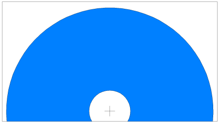
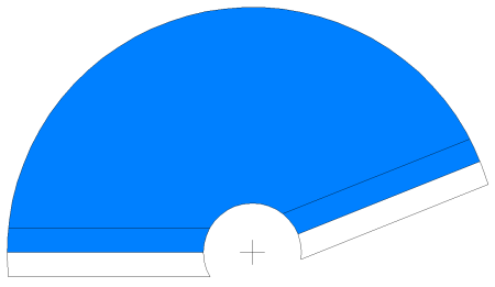 The cone is made from
sheet metal cut in the general form depicted here. The blue area is
what defines the cone, and overlap areas are indicated. To draw the
layout you need to know the large radius, the small radius, and the
angle formed by the straight edges of the blue zone, and in addition
you can arbitrarily decide how wide to make the overlap area.
The cone is made from
sheet metal cut in the general form depicted here. The blue area is
what defines the cone, and overlap areas are indicated. To draw the
layout you need to know the large radius, the small radius, and the
angle formed by the straight edges of the blue zone, and in addition
you can arbitrarily decide how wide to make the overlap area.
The large radius is equal
to the slant length of the cone.
The angle is calculated as:
Angle = 180 × MD ÷ Lcone
Note that the angle can end up larger or smaller than 180 degrees,
depending on the ratio of mouth diameter to wavelength of your design.
Finally the smaller radius is:
Rsmall = 180 × D ÷ Angle
where D is of course the diameter of the waveguide.
Now it's a simple matter to draw the figure on a piece of sheet metal,
cut it out, form it into a cone, solder it making sure the
overlap is the designed one, and then solder it to the waveguide.
Note that for clarity I drew pretty wide overlap areas in the figure.
In practice one would make the overlap a lot narrower, because it can
be hard to form a uniform cone when the overlap is too wide. For
example for my cones having roughly 350mm mouth diameter, I used an
overlap of 10mm.
A simplified cone design
 It can be a bit of a
chore drawing a precise angle on a piece of sheet metal. A good
workaround is to design the horn in such a way that the angle ends up
being exactly 180 degrees! This is simply done by selecting the mouth
diameter to be exactly 3 wavelengths, which often delivers a good
tradeoff between size and gain. The design equations for this
simplified horn are:
It can be a bit of a
chore drawing a precise angle on a piece of sheet metal. A good
workaround is to design the horn in such a way that the angle ends up
being exactly 180 degrees! This is simply done by selecting the mouth
diameter to be exactly 3 wavelengths, which often delivers a good
tradeoff between size and gain. The design equations for this
simplified horn are:
Large radius = 900 ÷ F
Small radius = D
The overlap
width is your choice. A suggested value is roughly 3% of the mouth
diameter.
 To draw this design on the sheet of metal, you simple mark the center
point spaced from the edge of your sheet by one half your
chosen overlap width, and then you take a compass and draw the
two radii. Ready! You cut out the piece, solder it together using
your chosen overlap width, and that's it.
To draw this design on the sheet of metal, you simple mark the center
point spaced from the edge of your sheet by one half your
chosen overlap width, and then you take a compass and draw the
two radii. Ready! You cut out the piece, solder it together using
your chosen overlap width, and that's it.
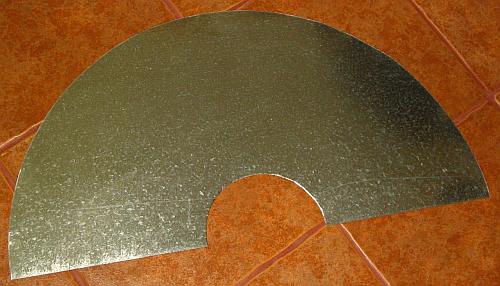
Note that again I have drawn this figure with an overlap wider than
what one would really use in practice, for clarity. The blue area in
this drawing is
the entire piece, including the overlaps. The photo of the ready cut
sheet shows how it looks for real, with a realistic overlap.
A horn antenna of this aperture has a theoretical gain of roughly
16dBi. Not bad for an antenna you can make from a tin can and a little
sheet metal!
Practical construction
 If a tin can having a
suitable size can be found, use it. Otherwise you have to make the
waveguide from sheet metal.
If a tin can having a
suitable size can be found, use it. Otherwise you have to make the
waveguide from sheet metal.
Ideally the material for the whole antenna should be thickly
silver-plated copper or brass sheet. Since this is unavailable to most
builders, copper sheet makes a replacement that is almost as good.
Brass sheet is less good but still OK. Zinc-plated steel, like I used,
is really not optimal, and I don't know how much performance I'm losing
because of its use. I can only say that the antennas work well
enough, giving a much better LTE signal than a pair of log periodic
yagis bought on the web.
If you have a choice between zinc-plated and tin-plated material, use
tin, because it's much easier to solder.
Don't use zinc-aluminium-plated steel, nor aluminium sheet, unless you
know a method to solder it.
A thickness of 0.3mm is fine, for plated steel sheet. With copper you
might have trouble soldering, if you chose a sheet that thick, because
copper is such a good heat conductor that it's hard to get such
a sheet hot enough for soldering, and while you
solder a place, the whole thing melts and comes apart! In this regard
plated steel sheet is far easier to work with. I have built horn
antennas from 0.1mm thick copper flashing. They work fine, but are
somewhat flimsy.
Do tin all parts properly before joining them.
Inexpensive N connectors are usually made from brass, and nickel-plated. The brass
solders very easily, while the nickel is much more reluctant to taking
solder. So I suggest that you file away the nickel coating from the
area of the connector body you need to solder.
It's important of course to use a connector that has a heat-resistant
insulator, otherwise it will deform while you solder.
The inside of tin cans is usually covered with a food-compatible
lacquer. I have found that it's easy to solder through it. It even
seems to act like flux. But if you have trouble soldering through it,
scrape it away around the connector opening.
Be sure to use low loss coax cables, when working in this frequency
range. Standard cable made for lower frequencies, like RG-213, causes
serious loss at UHF/microwave. Belden 9913 or LMR400 are about the
minimum acceptable choices. Keep the feedlines as short as possible.
Back to homo ludens electronicus.