Ferrite core loss in HF power applications
For broadband transformers in the high frequency range, the only really
usable core material is ferrite. Over the years several manufacturers
have developed and produced ferrite materials of various permeabilities
that can be used in HF power transformers, such as transmission antenna
baluns, power amplifier coupling and matching, or hybrid combiners, but
the manufacturers seem
to have striken a complot about not to publish the loss data for their
cores! While they do publish loss data for low-frequency cores made for
switching power supplies, the data sheets for almost all of their HF
cores do not include loss data for the radio frequency range. This
forces circuit designers to follow very imprecise rules of thumb, and
then experiment to find out whether the transformers will have
acceptable loss.
For several decades I designed my RF transformers in this way,
but
now (2019) I thought it was time to do something about it. So I spent a
good week of my time measuring the loss of 10 different ferrite cores,
in the frequency range of main interest to radio amateurs,
that
is, 1.8 to 54MHz, at flux densities in the range that would be used in
actual designs. This page presents the results, and my comments about
them.
The method
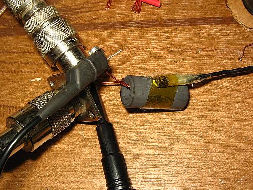 Each
core under test got a winding having a number of turns that would allow
driving the core to the desired level. This winding was fed from an HF
transceiver, using an antenna tuner when necessary, the coax cable then
going on to a dummy load. A 100:1 high
voltage scope probe connects to the winding, to measure the applied
voltage. The 100:1 ratio is necessary to keep the
probe from
burning out, since 10:1 probes normally don't survive enough RF voltage
to use them in this test. But the 100:1 ratio is also advantageous in
that the input impedance of such a probe is higher than that of a 10:1
probe, reducing the effect of the inductance of the probe tip and the
grounding clip and wire.
Each
core under test got a winding having a number of turns that would allow
driving the core to the desired level. This winding was fed from an HF
transceiver, using an antenna tuner when necessary, the coax cable then
going on to a dummy load. A 100:1 high
voltage scope probe connects to the winding, to measure the applied
voltage. The 100:1 ratio is necessary to keep the
probe from
burning out, since 10:1 probes normally don't survive enough RF voltage
to use them in this test. But the 100:1 ratio is also advantageous in
that the input impedance of such a probe is higher than that of a 10:1
probe, reducing the effect of the inductance of the probe tip and the
grounding clip and wire.
A temperature sensor was attached to each core under test, by means of
kapton adhesive tape and a small amount of thermally conducting grease.
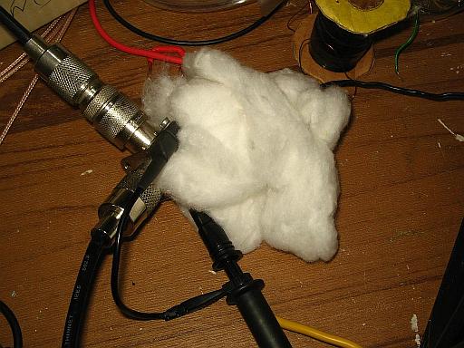 For
each mesurement the core was wrapped in cotton, to serve as thermal
insulation. Some time was allowed for the temperature to stabilize,
then a
specific RF voltage was applied, calculated to produce the desired flux
density in the core, whose dimensions were accurately measured.
After a certain time, typically 3 minutes, the drive signal
was
shut off, and again some time was allowed for the temperature to
stabilize. The temperature rise was used together with the heat
capacity of the core to calculate how much energy had been lost as
heat, and this value was divided by the core volume to get the power
loss per
cubic centimeter of core material.
For
each mesurement the core was wrapped in cotton, to serve as thermal
insulation. Some time was allowed for the temperature to stabilize,
then a
specific RF voltage was applied, calculated to produce the desired flux
density in the core, whose dimensions were accurately measured.
After a certain time, typically 3 minutes, the drive signal
was
shut off, and again some time was allowed for the temperature to
stabilize. The temperature rise was used together with the heat
capacity of the core to calculate how much energy had been lost as
heat, and this value was divided by the core volume to get the power
loss per
cubic centimeter of core material.
After each measurement the cotton was removed, and a fan was used
to cool the core back down to room temperature. The average total time
needed for each measurement was around 15 minutes, adding up to several
hours per core.
The test frequencies were the low band edges of each of the amateur
bands related in approximate or exact 1:2 ratio: 1.8, 3.5, 7, 14, 28
and 50MHz. On each frequency two tests were done, at flux densities
having a 1:2 ratio. The voltage was calculated for each core, so as to
give the same two levels of flux density in all cores. The drive
voltage was kept constant on all frequencies for each of the two
levels, so that the flux densities decreased in inverse proportion to
frequency. This reflects exactly how such cores get used in many
practical situations: At constant voltage and constant power throughout
the
frequency range.
In some cases some additional measurements had to be done at
additional levels of flux density,
when one of the two main measurements was in a range where
precision suffered.
The results
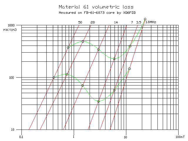
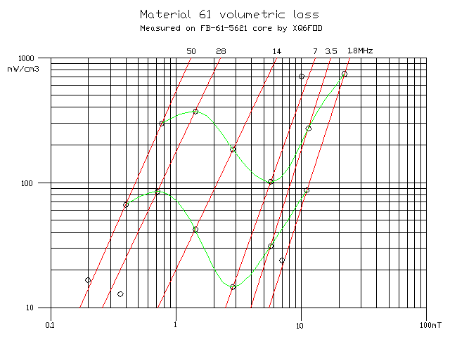 The
first core I tested was an FB-61-5621. This is a medium size cable bead
made of the material most commonly used by hams for low loss RF power
transformers. It has an initial permeability of 125. The part number is
the one used by Amidon, the distributor where I bought it. Fair-Rite,
the company manufacturing these cores, uses different part
numbers.
The
first core I tested was an FB-61-5621. This is a medium size cable bead
made of the material most commonly used by hams for low loss RF power
transformers. It has an initial permeability of 125. The part number is
the one used by Amidon, the distributor where I bought it. Fair-Rite,
the company manufacturing these cores, uses different part
numbers.
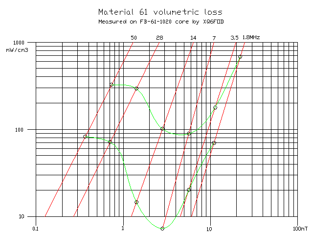
The little circles in the graph represent the actual measured values. I
drew the red loss curves as straight lines across the two measurements
that I thought are the most relevant. The manufacturers mostly draw
them as straight lines too, for the ferrites for which they do give
such curves, but I would be very surprised if these
should truly
be straight lines! But drawing these curves as they really
are,
slightly bent, would require at least 4 to 5 measurements per
frequency, and I didn't want to spend the rest of my life measuring
ferrite loss...
It's important to keep in mind, then, that in my graphs the parts of
each line that lie between the two measurement values used to draw it,
and close to them, are the most accurate, while any extensions of those
lines into a range where I made no measurement becomes increasingly
inaccurate. The important point here is that my measurements cover the
levels of flux density most likely used in practice, so that these
graphs can be used quite well for design.
The two green lines directly represent the volumetric loss of the
ferrite through the spectrum, at the two fixed drive levels. The upper
green line always represents a drive level such that a flux density of
22mT results on 1.8MHz, and the lower green line is at half that flux
density. So these green lines allow directly comparing the loss of one
ferrite to that of another. This is much easier to visually interpret,
than the red loss lines per frequency.
61 ferrite turned out to have a very idiosyncratic loss curve, with a
very low loss at 7MHz, the loss rising toward both higher and lower
frequencies, but dropping again when going beyond HF into the low VHF
range. I won't risk any explanation for this behaviour; I just present
the facts, as measured.
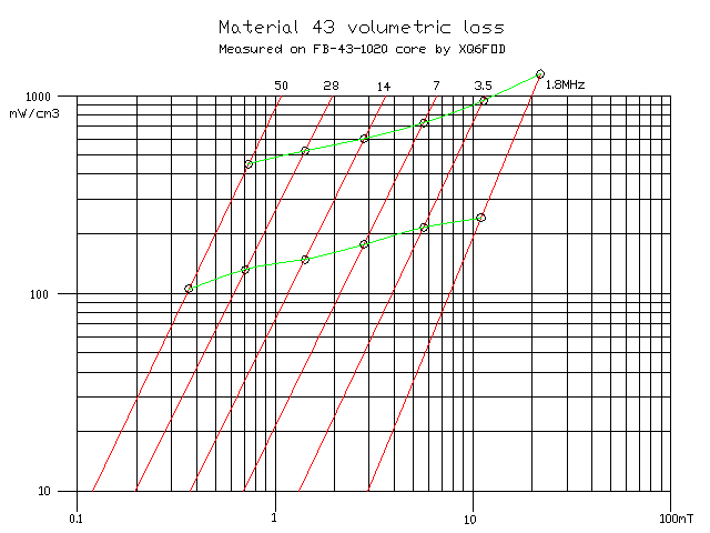
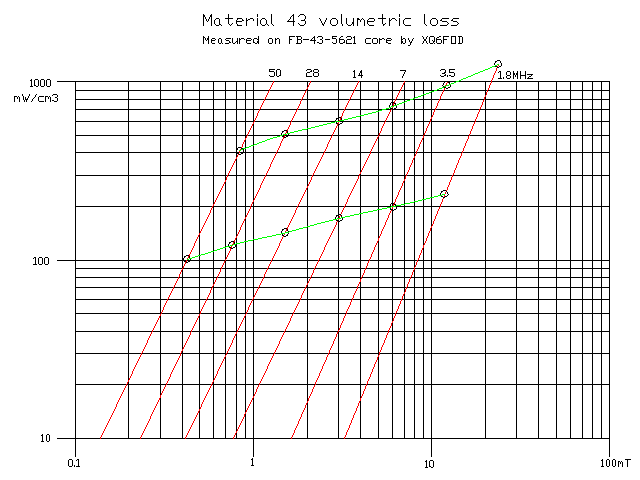 The
next core I measured was of the same nominal size, but
made from material
43, which has a much higher initial permeability of 850.
The
next core I measured was of the same nominal size, but
made from material
43, which has a much higher initial permeability of 850.
The behaviour of this material was extremely smooth, even, predictable,
almost boringly so. This looks nice at first sight - but the loss was
also higher than that of the 61 material, on all frequencies!
Note that at high flux density on 1.8MHz, the loss of material 43
turned out only out 60% higher than that of material 61. But on 7MHz,
where 61 has its sweet spot, 43 is 7 times more lossy than 61, at high
flux density, and a whopping 15 times more lossy than 61 at moderately
low flux density!
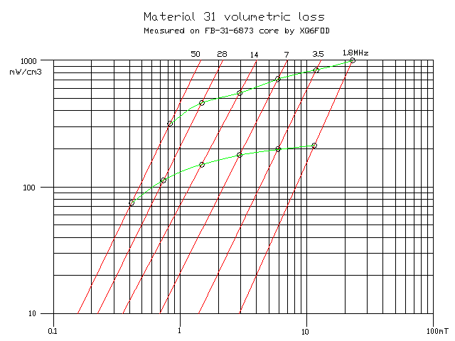 A
lot has been written in the last few years about material 31. Most RF
cores are made from nickel/zinc ferrites, while low frequency cores are
manganese/zinc ferrites. Manganese/zinc ferrite has fundamentally
higher permeability, its loss increases less with flux density
than in nickel/zinc ferrites, but it's also much more conductive than
nickel/zinc, and has far lower velocity of propagation, which leads to
dimensional resonance problems at RF. These two
latter characteristics make most manganese/zinc poor for RF
transformers.
A
lot has been written in the last few years about material 31. Most RF
cores are made from nickel/zinc ferrites, while low frequency cores are
manganese/zinc ferrites. Manganese/zinc ferrite has fundamentally
higher permeability, its loss increases less with flux density
than in nickel/zinc ferrites, but it's also much more conductive than
nickel/zinc, and has far lower velocity of propagation, which leads to
dimensional resonance problems at RF. These two
latter characteristics make most manganese/zinc poor for RF
transformers.
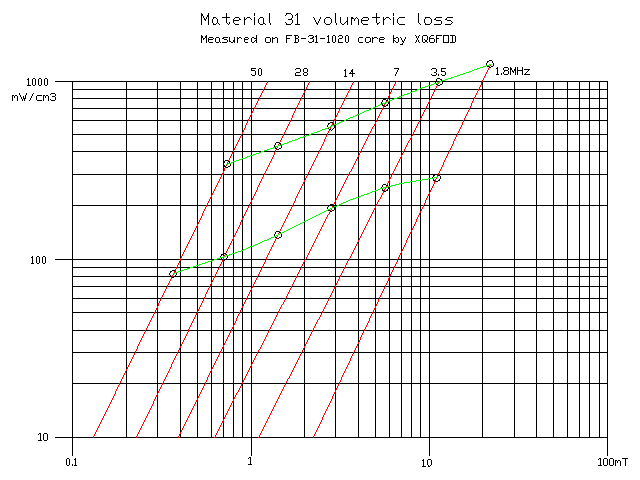
But all the characteristics of a ferrite material depend not only on
its basic formulation, but also on many details of the manufacturing
process, over which the manufacturer has ample control. And so the
Fair-Rite company came out with this material 31, which is an
RF-suitable
manganese/zinc material having a permeability of 1400, which is very
high for RF
use. I bough a small selection of material 31 cores, to try this
material.
The results show that the material very much resembles 43, in terms of
loss. The difference in loss is too slim to be enough reason to choose
between 31 and 43. But where its higher
permeability is an advantage, 31 is really the material to
use.
 Several
years ago I received a gift from a friend and fellow ham, whose health
was failing to
such a degree that he knew he wouldn't ever again need the ferrite
cores and other parts he had stocked. Nando, rest
in peace. His gift included a nice assortment of magnetic cores, among
them some "Ferronikits", which are kits of many cores of different
sizes, of a specific material and type, made by the company Ferronics.
Among these kits is one of material K binocular cores, and another of
material K toroids. I used one of the largest toroids to measure its
loss.
Several
years ago I received a gift from a friend and fellow ham, whose health
was failing to
such a degree that he knew he wouldn't ever again need the ferrite
cores and other parts he had stocked. Nando, rest
in peace. His gift included a nice assortment of magnetic cores, among
them some "Ferronikits", which are kits of many cores of different
sizes, of a specific material and type, made by the company Ferronics.
Among these kits is one of material K binocular cores, and another of
material K toroids. I used one of the largest toroids to measure its
loss.
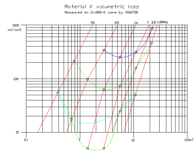
Material K is something special: A cobalt/nickel/zinc ferrite. It
has the same initial permeability as Fair-Rite 61, but thanks to a
small cobalt oxide addition and special processing it has exceedingly
low loss. The shape of its basic loss curve is similar to that
of material 61,
having a pronounced loss dip, in this case more toward 14MHz than 7MHz.
Unlike 61, material K has higher loss on 50MHz than on 28MHz - but
still lower than 61! Ferronics K is the lowest loss material I tested.
The two lowest measurement points are so low that they are in a range
where my test setup suffers from severe resolution problems: The
temperature rise was just 0.2°C, and my thermometer has a resolution
of 0.1°C, so the resolution-induced uncertainty is 50%! In the interest
of scientific honesty, I drew those points anyway - but don't trust
them. I drew the light blue loss curve that leaves out these two
suspect points. But I think that the actual loss curve probably lies
about halfway between the light blue and the lower green one.
On four frequencies I also had to make additional measurements at twice
the normal "high" drive level I used, to be able to get data for the
volumetric loss range that causes significant warming. That's the dark
blue curve. No other material could be driven to such a high flux
density on those frequencies without overheating in a matter of seconds.
If you can get Ferronics K cores, use them.
Note that the material K cores sold by Amidon are not
this Ferronics K material. They are rated at an initial permeability of
290, and I understand that they are made by yet another company. I
didn't test Amidon K material, because I don't have any of it. It would
have been interesting to test it.
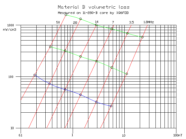 Another
of the Ferronikits I got from Nando contains toroids made from material
B. That's not an RF material. It's a high permeability manganese/zinc
ferrite, made for low frequency pulse transformers and the like. Just
for comparison, I tested the largest toroid of this kit, which is the
same size
as the material K toroid I tested.
Another
of the Ferronikits I got from Nando contains toroids made from material
B. That's not an RF material. It's a high permeability manganese/zinc
ferrite, made for low frequency pulse transformers and the like. Just
for comparison, I tested the largest toroid of this kit, which is the
same size
as the material K toroid I tested.
The characteristics turned out totally different from RF materials.
While the loss on 1.8MHz was roughly in the same range as that of RF
materials,
the loss of material B increases
with frequency, at constant
drive level, while in all RF materials it decreases.
So the loss of
material B in the high HF range and on 50MHz is very high. So
high in fact, that I had to run a third set of measurements, at an
extra low
drive level, to find out the loss in the range one could actually use
this material. That's the dark blue curve.
At sufficiently low drive levels, even this material could be used at
RF, but there is no reason to do so, since material 31 is available,
provides a high permeability, and much lower loss.
Note that I always have 1.8-54MHz applications in mind.
Instead if
just one band, or a a few bands, need to be covered, matters can change
a lot. In a pure 1.8MHz application, for example, material B would
be a good choice.
Given that I was already measuring non-RF materials, I also started
measuring the loss of a material 77 core. This is the main material
sold by Fair-Rite and Amidon for power applications in the 20-100kHz
range, typical for switchmode power supplies. It's a manganese/zinc
ferrite having an initial permeability of 2000. Some hams do
use
this material in RF applications. But my measurements turned out so
bad, that I decided to stop testing it, and I didn't draw a graph.
Suffice it to say that material 77 has similar loss characteristics as
material B, its loss rising with frequency at constant drive level, but
also the loss is much higher than for B!
Also some hams use material 73 in RF transformers. Unfortunately the
only cores I have in material 73 are small wire beads. They are too
small to let me accurately measure their loss with my setup, and also
the
diameter ratio of those beads is too high to produce reliable results.
Magnetic flux crowds in the small-radius areas of a core, and when the
diameter ratio is too high, this effect seriously impacts the accuracy
of material loss measurements.
 Having
run out of materials to test, I decided to test some cores made of the
same
materials but in other sizes. The 61 and 43 cores I tested
first
were of the same size, but the 31 core was slightly larger. Since I
have some material 61 cores of the same size as that 31 core,
I tested it.
Having
run out of materials to test, I decided to test some cores made of the
same
materials but in other sizes. The 61 and 43 cores I tested
first
were of the same size, but the 31 core was slightly larger. Since I
have some material 61 cores of the same size as that 31 core,
I tested it.
The result was surprising: While the loss curves have the same shape
than for the smaller 61 core, the volumetric loss is significantly
higher! This much
difference cannot come from my measurement setup. It's clear that
ferrites are not always very consistent, in terms of loss.
Material 61, like several other low permeability materials, can be
damaged by excessively intense magnetic fields. The
manufacturers
warn about this, but don't say how much is safe! Exceeding the limit
will increase both the losses and the permeability, according
to the lterature. Anyway this
core was taken fresh from the package for testing, so I'm sure that I
haven't applied a strong field to it. But could it be that it
was
exposed to such a field somewhere else, before I got it?
 Digging
deep in my treasure chest, I found three cores of identical size,
Amidon FB-1020, in all three most-used Fair-Rite materials: 61, 43 and
31. So I measured their loss.
Digging
deep in my treasure chest, I found three cores of identical size,
Amidon FB-1020, in all three most-used Fair-Rite materials: 61, 43 and
31. So I measured their loss.
The FB-61-1020 bead has loss curves very close to those of the
first,
smallest bead I tested. This was reassuring, as it suggests that there
are no hidden flaws in my measurement method, that would make it overly
size-sensitive. And it also suggests that my FB-61-6873 core
has
abnormally high loss.
 The
material 43 bead of the same size shows very much the same volumetric
losses as the much smaller bead I tested first. This suggests that
material 43 has better part-to-part consistency than material 61, but
it's not a good idea to judge this from just two samples...
The
material 43 bead of the same size shows very much the same volumetric
losses as the much smaller bead I tested first. This suggests that
material 43 has better part-to-part consistency than material 61, but
it's not a good idea to judge this from just two samples...
 And
the third in the group, the same-size material 31 bead, shows a loss
close to that of its smaller brother, but not as close as the two 43
siblings. This suggests a theory: Within each family (manganese/zinc or
nickel/zinc), the lower permeability members show wider
dispersion of their loss characteristics. And this might be due by the
low permeability being implemented by means of a distributed air gap
(more filler, less ferrite in the final mix), just like in powdered
metal cores, rather than by changing the basic formulation of the
ferrites. But I'm purely guessing this.
And
the third in the group, the same-size material 31 bead, shows a loss
close to that of its smaller brother, but not as close as the two 43
siblings. This suggests a theory: Within each family (manganese/zinc or
nickel/zinc), the lower permeability members show wider
dispersion of their loss characteristics. And this might be due by the
low permeability being implemented by means of a distributed air gap
(more filler, less ferrite in the final mix), just like in powdered
metal cores, rather than by changing the basic formulation of the
ferrites. But I'm purely guessing this.
The accuracy of these measurements
While I tried to work in a consistent, careful and repeatable manner
while measuring the loss of these cores, the result shouldn't be
considered to be highly accurate. There was always some heat loss
through the test winding, some extra heat generated by copper loss in
that wire, cotton isn't a perfect thermal insulator, the temperature
sensor isn't perfectly coupled to the core and does conduct some heat
away through its cable, and so on. In the very low loss range the
resolution of my temperature measurements is poor, the oscilloscope
used to measure the applied voltage only has
a 100MHz
bandwidth, which means that at 50MHz it could already have a
significant error, the scope probe is rated at 250MHz but was
used with its grounding clip pigtail, and so on. Despite all this, I
think that my
measurements are still usable, since the characteristics of
ferrite
materials themselves aren't highly precise. But one issue worries me
more than the sum of all others: I didn't find really trustworthy,
consistent information about the heat capacity of ferrite materials. I
found values between 500 and 1250 J/kg/K published on the web, many of
those
sources don't say what type of ferrite is meant, nor even whether they
mean
ferrite as in magnetic cores, or bulk ferrites of various types.
Narrowing it down from all I could find, I finally used a value of
750 J/kg/K for all my materials, but surely this is not precise. If the
heat capacity of any of the materials is different from this
value, the curves I drew for that material should be shifted
according to that difference.
In case one material has a very different heat capacity than another,
this might significantly affect the relative merits of them, making any
hard conclusions drawn from my graphs a bit dangerous.
Ferrites vary their loss according to temperature. My tests were all
done with the cores starting from my room temperature, about 21 to
22°C, and heating up at most to 45°C. So the loss measured is
representative for normal "cool" operation, but not for cores that are
running really hot.
Which material should you use?
Among the widely available materials (from Amidon and others), and
considering only the ones tested here, 61 has the lowest loss,
but
also the lowest permeability. That's no news at all.
What could be news to many people, is that the difference in
practical use between materials is less than one would think! Although
they can have a large difference in loss at a given flux density and
frequency, the loss also varies at a very high rate with flux density.
So, the flux density at which a core can operate, for a fixed
amount of heating, varies only slightly between the various ferrite
materials!
For example, let's assume that in a given application, with a given
core size, a volumetric loss of 200mW/cm³ is acceptable. You now have
to look at the graphs, and see at which frequency the ferrites have
their highest loss, and see what flux density they can take at that
frequency, for 200mW/cm³ loss. Let's do this now, for a 1.8-54MHz
application. Here is the table I got:
Material K: 15mT at 1.8MHz.
Material 61: 12 to 14mT at 1.8MHz.
Material 43: 10 to 11mT at 1.8MHz.
Material 31: 9.2-11mT at 1.8MHz.
Material B: 0.23mT at 54MHz, thus roughly 7.3mT at 1.8MHz.
Let's forget about material B, which isn't an RF material. All the
others fall in a range of 9.2 to 15mT, at 1.8MHz. That's an important
difference, but not a really dramatic one! In a critical application
you would want to get material K, if you can, and otherwise stick to
61, and see if you can get enough inductance from them at the low end
of the spectrum. Instead in a less critical situation you would use
any material you happen to have on hand, and just be sure to use enough
turns per volt to keep the flux density low enough. Using more turns,
or larger cores, reduces the upper frequency limit of a
transformer, and that's why in a critical application you need to be
careful with this. Equal-delay transmission line transformers
(Guanella) give you a whole lot more headroom in this regard.
Note that the selection of material is dependent on the
allowable volumetric loss. For example, let's assume that you will
make a very small transformer. In these a much higher volumetric loss
is acceptable, due to their higher surface-to-volume ratio, unless the
insertion loss becomes a problem from the point of view of signal
attenuation. Let's assume you can tolerate
1000mW/cm³. In this case, at 1.8MHz:
Material K: 28mT
Material 61: 20.5 to 23mT
Material 31: 20 to 22mT
Material 43: 20 to 21mT
Except for our clear winner, Ferronics K, the other three are pretty
much in a tie!
And now let's go to the other extreme, when you have large cores, no
forced-air cooling, and continuous operation, so that you can only
accept 50mW/cm³ of core loss:
Material K: 10mT
Material 61: 8 to 9mT
Material 43: 5.7 to 6.2mT
Material 31: 4.8 to 6mT
Material K wins again, but 61 is close, the other two falling way
behind. Note that both K and 61 are actually limited by the high
frequency end, having slightly higher loss there than at the low end,
at this low drive level.
And if you have an application that only needs a smaller frequency
range, things change again.
This entire page is just about the loss of ferrite cores, but core
loss is just one of several things you need to keep in mind when
selecting the best material for a given application, and then select
the shape and the size of the core. Here are some other considerations:
Initial permeability: The materials tested here vary between 125 and
5000. That's a huge range! Some people think "the bigger the better",
other's think "enough is enough", but few realize all the
implications of using materials of different permeabilities. Firstly,
it's important to understand that the permeabilities really vary only
in the lower frequency range. By 50MHz all of these ferrites have
nearly the same permeability. Also at the low end of our frequency
range the differences are already smaller than the very low frequency
initial permeabilities suggest:
K: 125, highly inductive
61: 135, highly inductive
43: 550, with significant resistive component
31: 1100, with high resistive component
Note that these are the initial
permeabilities, that is, the ones the materials show at extremely small
flux density. At higher drive levels they change - specially the
resistive component grows much larger. This effect is stronger in
nickel/zinc ferrites than in manganese/zinc ones - you can see it by
comparing the steepness of the 1.8MHz loss lines of 61 and 31 ferrites.
That of 61 is much steeper.
A higher permeability can save the day, which is why many people
love material 31. But it can also be a big liability. For
example, when
there is any net DC present in the windings. At a given core size,
turns number and DC flowing in those turns, the DC flux density in the
core is
in direct proportion to its very-low-frequency permeability. Said
clearly, a 31 core will have to carry 11 times as much DC flux as a 61
core! Very often this is critical in power amplifiers. While a 31 core
would be totally saturated by a given DC, a 61 core might handle
it comfortably. With low permeability ferrite you
can often
just forget about imbalance currents in bifiliar chokes, for example -
they typically won't cause trouble. Instead with high permeability
ferrite even a small imbalance in a push pull amplifier might saturate
the core!
Also an excessive permeability extends the response of a transformer
down into an uneeded, and often unwanted, frequency range. It's
typically an aid to amplifier stability to use transformers that have
just enough bandwidth.
This extension of frequency response can be a real problem, when it
extends so low that it reaches the higher components of the envelope
signal, in transformers or chokes that carry a DC supply. In that case
distortion can be caused, which manifests
in splatter. So there are many good reasons to design
transformers in such a way that they respond only over the desired
frequency range, and not much beyond. And that often means that a
specific permeability is optimal for a specific design. Not the highest
one and not the lowest one, but the right one.
Another consideration is thermal effects. When a core runs warm, it
changes its characteristics. In an extreme case, it can reach its Curie
temperature, and at that point you no longer have a magnetic core, and
the amplifier blows up! Material 43 has a Curie temperature of only
135°C. Material 31 is even lower! Instead material 61 and
material K both have it above 350°C, so it will never be reached in any
normal circuit. Now you might say that 130°C also won't ever be
reached. Be careful about that, though. Ferrites are poor thermal
conductors, and the temperature inside the
core can
get much higher than that on its surface! The larger a core
is, the more severe this effect becomes. So, in applications that
might run very hot, you might be forced to use a material that has a
high enough Curie point.
Cost and availability are powerful factors in deciding what core to
use. Materials 61, 43, 31, and a few more, are widely available through
Amidon and a few other distributors. Some amplifier builders have used
Laird 28 material, which is available from some mainstream parts
distributors. It has slightly lower permeability than 43 and might be a
good choice, but specifications given by Laird are very thin. The
complex permability graph they publish suggests that the material is
less lossy than 43, but that's just the initial permeability, and it
says
little about the loss at higher flux densities. I don't have any Laird
28 cores here, so I can't test them. The same happens with cores from
manufacturers like TDK, Ferroxcube, Kaschke, and several others. As
long as I can't find a place where I can order them online, paying by
Paypal or the like, and have them shipped to me by mail for a
reasonable charge, I can't use those cores.
The cost of material 43 and 31 tends to be the same, while 61 is more
expensive. That's a good reason to avoid 61when you can. On the other
hand, in many circuits the cost of ferrite cores is small compared to
that of other parts, such as high power transistors. This makes it
reasonable to choose the best cores, regardless of a few dollars
difference in their total cost.
Saturation flux density is of no importance in pure RF work, because a
core will dramatically overheat at flux densities far lower than its
saturation level. The exception could be pulsed operation at a very
high peak-to-average ratio, but I'm writing this page mostly for
homebrewing radio amateurs, and we hams don't use such narrow pulses.
But
always keep in mind the problems associated with DC. If
there is any chance that DC will flow in a winding, you need to
evaluate what effects it will cause. A material combining high
saturation flux density with low permeability tolerates the highest DC
drive. But don't forget that materials like 61 and K are degraded by
high flux density, and we are not told how much is safe!
A minor point to keep in mind is the electrical conductivity of the
materials. Generally nickel/zinc ferrites are essentially good
insulators, while manganese/zinc ferrites are bad conductors. If you
use any manganese/zinc ferrite, including material 31, you need to keep
in mind that it is slightly conductive, and insulate it where needed.
Life has never been easy. And ferrite cores are worse than life in that
regard.
Back to homo ludens electronicus.