 Electrolytic capacitors
are by far the electronic parts that suffer aging soonest. If you have
any electronic equipment that over the years has degraded its performance,
developed quirks, sometimes ending in complete failure, the chances are
good that one or more electrolytic capacitors inside it have degraded,
causing the problem. Electrolytic capacitors age in several ways: They
can become electrically leaky, causing a DC current through them that can
make them blow up. They can shift in capacitance value. But the most common
way they degrade, by far, is by unduly increasing their equivalent series
resistance, which is the undesired internal resistance that appears
in series with the wanted capacitance at a given frequency.
Electrolytic capacitors
are by far the electronic parts that suffer aging soonest. If you have
any electronic equipment that over the years has degraded its performance,
developed quirks, sometimes ending in complete failure, the chances are
good that one or more electrolytic capacitors inside it have degraded,
causing the problem. Electrolytic capacitors age in several ways: They
can become electrically leaky, causing a DC current through them that can
make them blow up. They can shift in capacitance value. But the most common
way they degrade, by far, is by unduly increasing their equivalent series
resistance, which is the undesired internal resistance that appears
in series with the wanted capacitance at a given frequency.
The ESR of an electrolytic capacitor is normally just a small fraction of an Ohm for a high capacitance, low voltage capacitor (such as a 1000µF, 16V cap), and can be as high as two or three Ohm for a low capacitance, high voltage cap (1uF, 450V). When the capacitor ages, this resistance increases, and it often does so in such a dramatic way that the equipment completely ceases to function or even blows up semiconductors. It's very common to find capacitors that have degraded to 100 times their normal resistance, while their capacitance remains fine! On a typical capacitance meter they will measure close to their correct values, but they are completely bad! This is where the ESR meter comes in: It measures the equivalent series resistance of the capacitor, almost independently of its capacitance.
An additional beauty of an ESR meter is that in almost all cases it
can check capacitors while they are in the circuit! This is so because
a good capacitor would measure almost like a short circuit, and so any
other parts connected in parallel will have minimal influence on the measurement.
These are the features that make an ESR meter an irreplaceable tool for
troubleshooting electronic equipment.
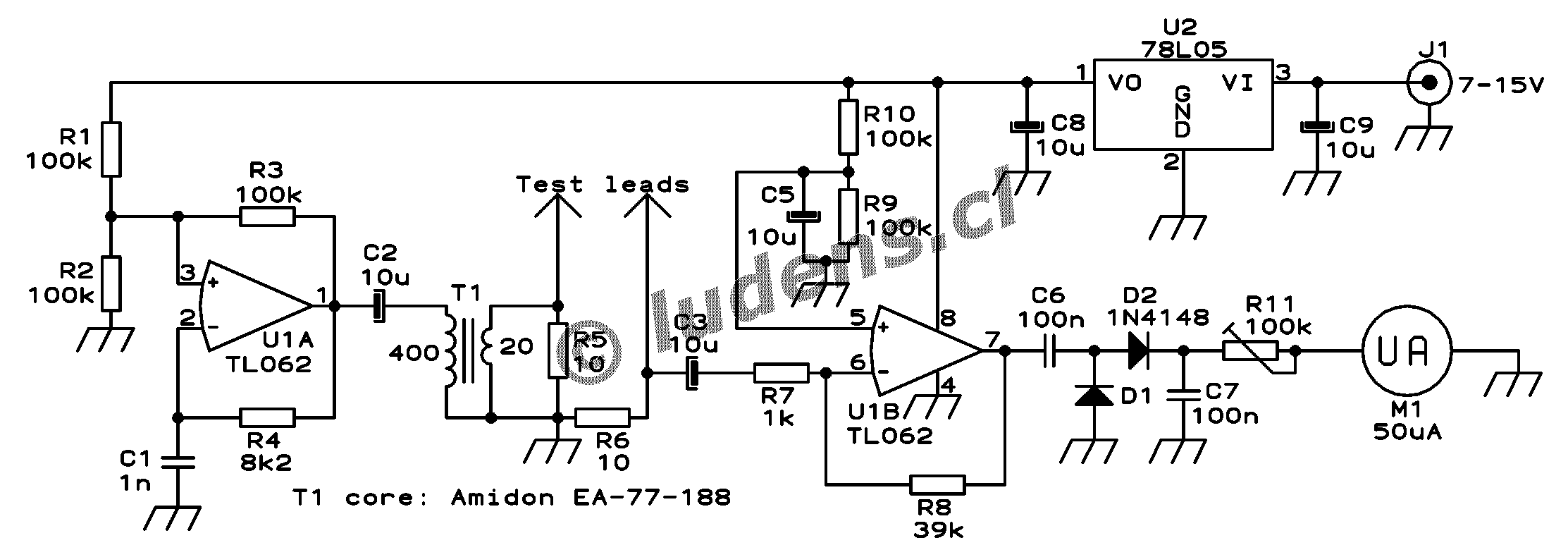
Here is the schematic, which you can click on to get a larger version for printing.
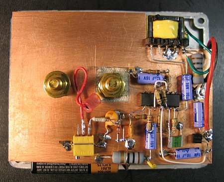
One section of a dual low power operational amplifier is used as a square wave oscillator. A small ferrite core transformer is used to step down the voltage and provide the necessary low impedance output. A 10 Ohm resistor loads the output to absorb inductive spikes from the transformer, which could cause a false reading for low value capacitors. The other section of the op amp amplifies the signal that gets through the capacitor being tested, and its output is rectified and applied to a 50µA galvanometer through a calibration potentiometer. A small 5 Volt regulator maintains the supply constant while the instrument is being powered from anything between about 7 and 15 Volt. I power the meter from the 13.8V bus which I have in my workshop, but if you prefer, you can use a 9V battery instead, connected through a switch. The power consumption of this circuit is so low that a 9V battery should last at least 100 hours.
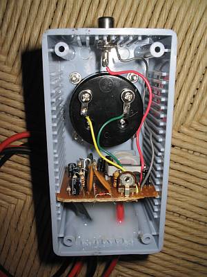 Building this
ESR meter is simple and straightforward. I assembled the circuit on a scrap
piece of project board, and used a small plastic box to install the board
and the meter. The only part that could pose problems to inexperienced
builders is the transformer. I made mine using an Amidon ferrite core,
type EA-77-188, which is a tiny double-E core having a cross section of
22mm2, and external dimensions of about 19x16x5mm total.
I used the nylon bobbin that Amidon delivers with it, wound a primary winding
consisting of 400 turns of AWG #36 wire, and as secondary I wound 20 turns
of AWG #26 wire. If you have a larger or smaller core, you can adjust the
turn numbers in inverse proportion to the cross section area. The wire
size isn't critical - the gauges I used are about 3 or 4 numbers thicker
than necessary, while at the same time this bobbin has room for wire at
least two numbers thicker than the ones I used. Thus, you can choose from
about 6 different wire gauges for each winding, with negligible impact
on the performance.
Building this
ESR meter is simple and straightforward. I assembled the circuit on a scrap
piece of project board, and used a small plastic box to install the board
and the meter. The only part that could pose problems to inexperienced
builders is the transformer. I made mine using an Amidon ferrite core,
type EA-77-188, which is a tiny double-E core having a cross section of
22mm2, and external dimensions of about 19x16x5mm total.
I used the nylon bobbin that Amidon delivers with it, wound a primary winding
consisting of 400 turns of AWG #36 wire, and as secondary I wound 20 turns
of AWG #26 wire. If you have a larger or smaller core, you can adjust the
turn numbers in inverse proportion to the cross section area. The wire
size isn't critical - the gauges I used are about 3 or 4 numbers thicker
than necessary, while at the same time this bobbin has room for wire at
least two numbers thicker than the ones I used. Thus, you can choose from
about 6 different wire gauges for each winding, with negligible impact
on the performance.
Considering that the transformer is so uncritical (because it runs at very low power), feel free to use any small ferrite core you have on hand, as long as it has no air gap. Dead PC power supplies and old monitors or TVs are great sources for such cores. Do not use an iron core, because it would probably have far too much loss at 50kHz.
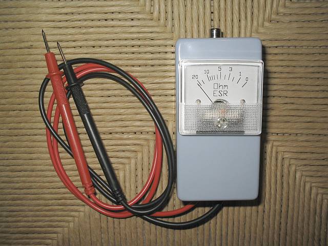
The test leads are soldered into the circuit, and fixed in place using hot melt glue. Soldering them is much preferable over using any sort of connectors, because this meter easily detects resistance as low as 0.1 Ohm, and a connector can easily vary its resistance more than that! By the way, this set of test leads was bought as standard tester replacement leads, for very little money.
The meter is a reasonably good one rated at 50µA full scale, which
I had on hand. If you find a cheap VU meter that works well, you can use
it, of course. If you prefer to use a 100µA meter, change R11 to
50k. I used a trimpot for R11, but you might want to use a panel-mount
potentiometer instead, which would allow fine adjusting the full-scale
point if your meter happens to be unstable. If you use a cheap meter I
would recommend this.
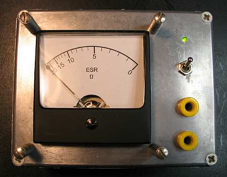 After setting
up this page, I started getting lots of mail from other people who built
their versions of the ESR meter. Curt Terwilliger, W6XJ, sent some high
quality photos of his work. He found the box with the meter and banana
jacks in his junk box, so needed just a little electronic tinkering to
transform that thing into an ESR meter! The scale was redrawn, and the
necessary guts installed behind.
After setting
up this page, I started getting lots of mail from other people who built
their versions of the ESR meter. Curt Terwilliger, W6XJ, sent some high
quality photos of his work. He found the box with the meter and banana
jacks in his junk box, so needed just a little electronic tinkering to
transform that thing into an ESR meter! The scale was redrawn, and the
necessary guts installed behind.
He powered it from a 9V battery and even added a LED!
 Curt used
an existing transformer taken out of an old PC power supply. It has much
lower impedance, and slightly lower turns ratio than my transformer, but
works well enough.
Curt used
an existing transformer taken out of an old PC power supply. It has much
lower impedance, and slightly lower turns ratio than my transformer, but
works well enough.
Instead of the TL062, he used a TL084. That's a change I would not recommend, because the TL084 is not rated to work at the low voltage used here, so it's a matter of luck and tolerances that it works at all! Also, given the much higher saturation voltage of that opamp's output section, Curt had to modify the value of R8 to get a reasonable scaling on the meter. Before that, his instrument was driven into saturation, compressing the scale. But finally it worked for him, showing that builders can take quite a bit of artistic liberty and still get a useful result!
Curt used flat-style dead-bug construction on an unetched piece of PCB,
obtaining a low profile circuit.
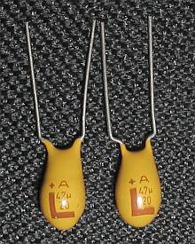 What difference
do these two tantalum caps have? If you look at them, you will notice that
they look alike almost as much as two eggs laid by the same hen. The two
come from the same factory, and should belong to the same manufacturing
batch. The two came in a bag of 20 equal ones I bought at a local store.
Measured on a capacitance meter, both have almost exactly the same capacitance,
very close to their rated 47µF. Measured with a common ohmmeter,
both have essentially infinite insulation resistance. But when measuring
their ESR with my newly built meter, I was in for a surprise: The one at
right, like the other 18 caps not shown in this picture, has an ESR of
about 0.2 Ohm, which is quite normal for a tantalum cap of this size. But
the one on the left is a bad apple (or egg?) and has a whopping 15 Ohm
ESR!!! It has a manufacturing defect, impossible to tell without measuring
the ESR. If I had placed this capacitor in a circuit that exposes it to
significant ripple current, it would have exploded, which is a trick tantalum
caps just love to perform. Worse than that, if I had used it to filter
a signal, it simply wouldn't have worked well, and I would have never suspected
why my circuit didn't perform as calculated! After this surprise, I must
advice you to test every component before putting it into a circuit, and
never assume that a part that comes fresh from the factory is actually
a good part!
What difference
do these two tantalum caps have? If you look at them, you will notice that
they look alike almost as much as two eggs laid by the same hen. The two
come from the same factory, and should belong to the same manufacturing
batch. The two came in a bag of 20 equal ones I bought at a local store.
Measured on a capacitance meter, both have almost exactly the same capacitance,
very close to their rated 47µF. Measured with a common ohmmeter,
both have essentially infinite insulation resistance. But when measuring
their ESR with my newly built meter, I was in for a surprise: The one at
right, like the other 18 caps not shown in this picture, has an ESR of
about 0.2 Ohm, which is quite normal for a tantalum cap of this size. But
the one on the left is a bad apple (or egg?) and has a whopping 15 Ohm
ESR!!! It has a manufacturing defect, impossible to tell without measuring
the ESR. If I had placed this capacitor in a circuit that exposes it to
significant ripple current, it would have exploded, which is a trick tantalum
caps just love to perform. Worse than that, if I had used it to filter
a signal, it simply wouldn't have worked well, and I would have never suspected
why my circuit didn't perform as calculated! After this surprise, I must
advice you to test every component before putting it into a circuit, and
never assume that a part that comes fresh from the factory is actually
a good part!
 The first true
troubleshooting use for my new ESR meter was in rejuvenating my dear oscilloscope.
That one is a 30 year old Tektronix, which I bought in bad condition 20
years ago and fixed. For those 20 years I hadn't done much to it, and over
the years several minor functions had failed, but the biggest problem was
that the trace had degraded to a fuzzy broad strip, its intensity modulated
by hum and by the signal being measured! This really smelled like degrading
electrolytic capacitors, no wonder after 30 years.
The first true
troubleshooting use for my new ESR meter was in rejuvenating my dear oscilloscope.
That one is a 30 year old Tektronix, which I bought in bad condition 20
years ago and fixed. For those 20 years I hadn't done much to it, and over
the years several minor functions had failed, but the biggest problem was
that the trace had degraded to a fuzzy broad strip, its intensity modulated
by hum and by the signal being measured! This really smelled like degrading
electrolytic capacitors, no wonder after 30 years.
With my ESR meter I quickly found five electrolytic capacitors which
had degraded a lot. Interestingly, four of them were of the same brand
and can size, even if of two different values - probably there was a sealing
problem! Of these capacitors, one had 4 Ohm ESR, one had 6 Ohm, one 7 Ohm,
and the other two had such high ESR that the meter wouldn't even deflect!
The other electrolytic caps in the oscilloscope were all still healthy,
with ESR values well below one Ohm for most, and close to one Ohm for a
few low capacitance, high voltage ones. I replaced the bad ones, and this
gave me back a well defined and stable trace! Also one of the dead functions
revived. The other dead functions were due to two open resistors, one value-shifted
resistor, and two open transistors, which I found by conventional troubleshooting.
After fixing all that, and spending two days completely realigning the
instrument, it's again as good as new! But that's a matter for another
web page...