15-Band World Receiver
 In the year 2010, thirteen
years before writing this article, I happened to have a lazy day, and
decided to play a little with electronics. At first it wasn't clear
what exactly I would play with, but rummaging through my junk box I
happened to re-discover a bunch of old MPF201 transistors. No, that's
no typo! They are not the much better known MPF102 JFETs, but
the pill-shaped MPF201 dual-gate MOSFETs. When I was
a university student, several decades ago, I had gotten a chance to buy
all the ones a store in my town had, for very little money. The store
owner was glad to get rid of them, since nobody else wanted those
strange
things. I bought them because it's always good to have a bunch of RF
dual-gate MOSFETs at hand, but had never really used any. So, playtime
began!
In the year 2010, thirteen
years before writing this article, I happened to have a lazy day, and
decided to play a little with electronics. At first it wasn't clear
what exactly I would play with, but rummaging through my junk box I
happened to re-discover a bunch of old MPF201 transistors. No, that's
no typo! They are not the much better known MPF102 JFETs, but
the pill-shaped MPF201 dual-gate MOSFETs. When I was
a university student, several decades ago, I had gotten a chance to buy
all the ones a store in my town had, for very little money. The store
owner was glad to get rid of them, since nobody else wanted those
strange
things. I bought them because it's always good to have a bunch of RF
dual-gate MOSFETs at hand, but had never really used any. So, playtime
began!
Dual-gate MOSFETs work pretty well as variable-gain amplifiers, for
example in IF amplifiers of radios. So, to see what these things are
capable of, I grabbed a small scrap of unetched circuit board, some
nondescript 10.7 MHz IF transformers, and built a two-stage IF
amplifier, in
dead-bug style. It worked quite well. And the rest is history, as they
say!
During three years I kept adding parts, ran out of space on that little
board, added more boards, added even more parts, and after a
lot of play time the thing grew into a fully fledged,
microprocessor-controlled, synthesized, pretty good receiver,
that covers all short
wave and medium wave AM broadcast bands!
Complete with 100 memories, notch filter, and whatnot.
The idea was to make a modern classic, by using an eclectic mix of
modern and antique technology, building it into a chassis,
and installing that chassis inside a beautiful lacquered wooden
cabinet, maybe even one in cathedral style. But when the radio was
technically ready, working perfectly, I got lazy, and never built that
nice cabinet! So the radio lingered in my closet for years, in the
growing section reserved for half-finished projects, until I decided to
use it as it is, without a cabinet, and placed it on my bedside stand,
where it now serves duty to lull me into sleep every evening, with the
classical and irreplaceable sound of shortwave broadcasts.
I delayed writing and publishing a web page about it until now, in
2023. Given that apparently I will never get to building a cabinet for
it, I
decided to publish it as it is, naked, bare bones, as it has been for
10 years now.
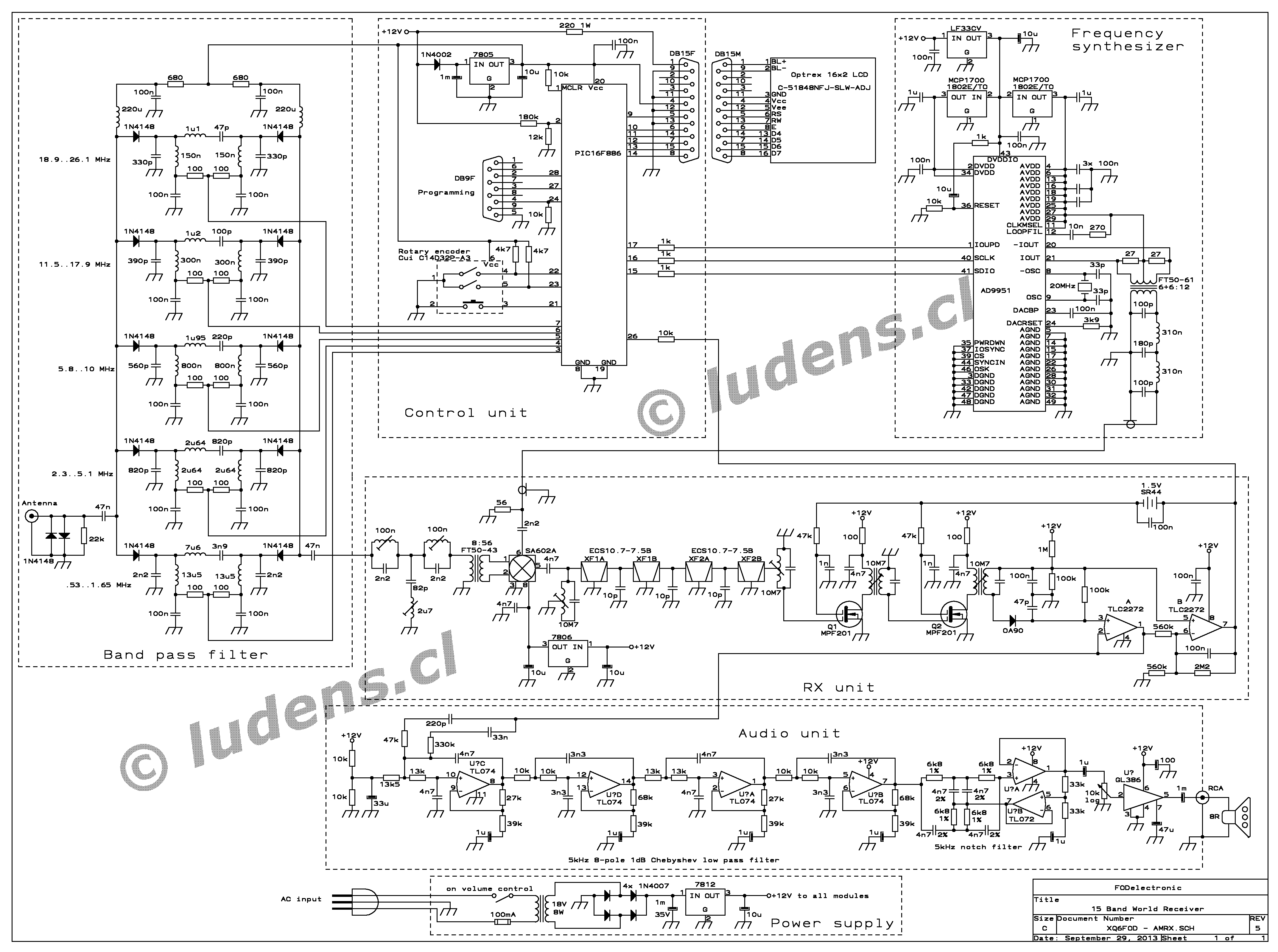
 Here
is the complete schematic diagram, of course much too small to be
legible, but you can click it to get the full size version.
Here
is the complete schematic diagram, of course much too small to be
legible, but you can click it to get the full size version.
The antenna signal first goes through a 6-pole bandpass filter. There
are just 5 filters, despite this being a 15 band radio. Each filter is
used for a relatively broad frequency range, and most of these ranges
include cover several broadcast bands. The filters are diode-switched.
The signal then goes through a 6-pole IF trap, and then via an
impedance matching transformer to an SA602A doubly balanced mixer. I
was a bit hesitant at first to use this mixer IC, due to its fame of
having a relatively
small dynamic range when compared to diode or JFET mixers. But it
turned out to work plenty well enough for this task, and the simplicity
it provides is appealing. The only downside really is that I had to add
a dedicated voltage regulator IC for it, to provide the mixer with a
supply voltage it likes.
The IF signal delivered by the mixer goes through an 8-pole crystal
filter, made up from two cascaded 4-pole filters, each consisting of
two 3-legged crystals. The filter provides about 12kHz bandwidth, which
I find optimal for AM shortwave broadcast reception, because it
will pass the carrier of a signal even when the
receiver is
tuned 5 kHz high or low, which in many cases allows rejecting
interference from a neighboring station by simply tuning to the far
side of it.
After the IF filter comes the circuit with which the whole project
began: The two-stage IF amplifier using two MPF201 dual-gate MOSFETs.
It's a very simple circuit, and it uses a very old, time-honored
technique that comes from the age of the very first tube radios: A bias
battery! Dual-gate MOSFETs need an AGC signal that gets a
little below their source voltage, to provide a wide gain adjustment
range. This is most commonly done by lifting the source voltage a
little above ground, using various bias schemes, but I found that the
MPF201 likes high supply voltages, and since my main supply is
only 12V,
I decided to simply leave the sources at ground to let the MOSFETs get
the full 12V, and place a
little coin cell in series with the AGC line, so that the bias
voltage can go 1.5V below ground! Since the gates are insulated, no
current is ever drawn from this cell, and it will last as long as its
shelf life allows. I used a silver oxide cell, and expect it to last
for
several decades, probably longer than I will last.
The detector is a conventional one, using a real, true, old germanium
diode.
This is another element that defines this receiver as a modern classic!
To load the detector with a high impedance, an operational
amplifier is used as a buffer, and another operational amplifier
(actually the second section of the dual op amp IC) acts as integrator
to
provide the proper AGC voltage.
The audio chain looks pretty long, but really isn't that complex. It
first features a 5kHz low-pass filter, which suits the audio bandwidth
used by most AM stations (although some are wider). This is an 8-pole
filter too, giving a pretty sharp cutoff, and it's built around a quad
op-amp. And after it comes a special feature of my radio: A
fixed-tuned, sharp and deep 5kHz notch filter, which totally eliminates
the nasty high-pitched carrier beat that usually plagues shortwave
broadcast
reception! Since almost all broadcast stations use very
accurate frequency control, these beat tones are almost always very
precisely at 5kHz, and so they can be rejected by such a
fixed filter. This
notch filter is built around a dual op-amp.
The end of the audio chain is a GL386 power amplifier chip. This is an
equivalent of the very well known LM386, but I found the GL version,
made by Goldstar/LG in Korea, to have lower distortion than the
original LM versions found in my junk box! It's just a
fractional watt
amplifier, but when using a decent speaker this is plenty enough power
to give room-filling volume.
The local oscillator is an AD9951, a high-performance Direct Digital
Synthesizer, not to be confused with the much more humble AD9851. It's
the most expensive part of this radio, and since it comes in a 48-pin
SMD package that has a pin pitch of 0.5mm, and has a metal patch on its
belly that needs to be soldered to a small heatsink, it's not easy to
mount for an aging homebrewer. It took me three attempts to get all
pins soldered down, without shorts!
I used the internal reference oscillator of the AD9951, with an
external 20MHz crystal, and used the internal PLL frequency
multiplier of the chip to produce a 400MHz clock signal, which drives
the DDS proper to synthesize a 14-bit resolution sine wave in the range
of roughly 11 to 37 MHz. The radio uses high-side
oscillator injection on all bands, but this could be easily changed in
the firmware, if so desired.
There is no trimmer to fine-tune the crystal frequency. Instead the
software in the controller allows setting the required compensation for
any frequency shift of the crystal. By the way, the software also
allows to shift the IF frequency, in case the crystal filter isn't
spot-on, or shifts over time.
The output of the DDS chip goes through a balancing transformer and a
5-pole low-pass filter, and then on to the SA602A mixer.
The DDS chip is powered through three separate, dedicated voltage
regulators! One provides the 3.3V required for its input/output
circuitry, while the other two are 1.8V regulators, one for the digital
and one for the analog side. This radio is really a celebration of
3-terminal regulators! There are a total of six of them.
The controller is based on a very inexpensive 28-pin PIC
microcontroller. It does everything: Reading the encoder used for all
user input, driving the display, controlling the DDS, switching the
bandpass filters, storing the memory frequencies, sensing the AGC
voltage to display a signal strength indication, and it even senses the
supply voltage, to quickly store the operating conditions (frequency,
memory channel, tuning mode) into non-volatile memory when the user
switches off the radio, while the voltage is falling!
It also supports low-voltage in-circuit programming, and a DB-9
connector is included to reprogram the PIC without having to remove it.
This allows correcting for aging-induced frequency shift of the master
oscillator
crystal or the IF filter, changing the band limits when the broadcast
frequency ranges are changed, making improvements, adding features,
fixing bugs - but I haven't found any bugs in 10 years!
The display is an extra large, backlit alphanumeric LCD, that has 2
lines of 16 characters each. It's conected by means of a DB-15
connector, so that it can be easily disconnected when taking out the
chassis from the cabinet - if I ever build a cabinet, that is!
All of the radio's frequency-related operations, like tuning, band
switching, memory programming, recalling and deleting, are done with a
single optical step encoder that also has a pushbutton function. I
chose the
more expensive optical encoder because I have seen too much trouble
with mechanical encoders, even after just a short time of use.
The optical ones instead work
flawlessly, virtually forever. That's important in a radio that needs
lots of tuning up and down in the bands, hunting for interesting
stations.
Oh, let's not forget to mention that the PIC also has its dedicated 5V
regulator! Its input is buffered by a large electrolytic capacitor and
a diode, to keep the supply to the PIC going for a moment while it's
already coming down for the rest of the radio, so that the PIC has time
to write the operational data into its non-volatile memory.
The last part of the radio is the power supply. It's a totally
standard, run-of-the-mill transformer-based, regulated 12V power
supply, using yet another 3-terminal regulator!
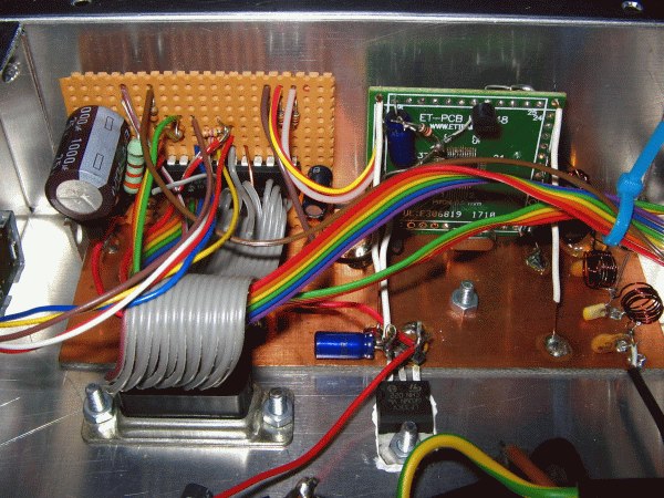
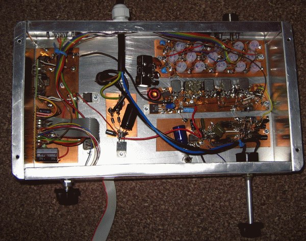 Here you can see the
general layout under the chassis. On the left is a PCB material scrap
to which I soldered the perfboard carrying the controller
circuit, an SMD carrier board that carries the frequency
synthesizer, and also its lowpass filter. The TO-220 soldered to it and
screwed to the chassis is the 3.3V regulator. It needs heatsinking
because it's dropping 8.7V, and the DDS chip it powers consumes a
considerable current.
Here you can see the
general layout under the chassis. On the left is a PCB material scrap
to which I soldered the perfboard carrying the controller
circuit, an SMD carrier board that carries the frequency
synthesizer, and also its lowpass filter. The TO-220 soldered to it and
screwed to the chassis is the 3.3V regulator. It needs heatsinking
because it's dropping 8.7V, and the DDS chip it powers consumes a
considerable current.
The little board scrap in the middle carries the power supply parts:
Rectifier diodes, capacitors, and the 12V regulator, which is
also bolted to the chassis.
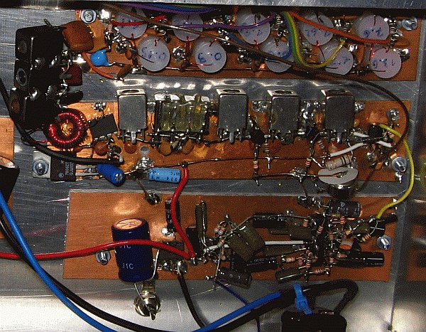
The right top unit is the bandpass filter board, full
of homemade polyethylene coil formers. The three IF cans on
its left are the IF trap.
The right center board is the receiver chain. At its left is the
impedance matching transformer (toroidal), the mixer IC, the 6V
regulator powering it, then comes the IF filter with its input and
output tanks, then the two IF amplifier stages, the detector, and the
op amp circuit that provides the AGC and buffers the audio signal. The
bias battery is on the lower right of that board.
And lastly, the board in the lower right of the chassis contains all
the audio circuitry.
The left knob is attached to the optical encoder, while the right one
is the volume control potentiometer, with on/off switch. Totally
classical! The antenna connector is on the upper right, the PIC
reprogramming connector is on the upper left, and the power cable, a
safe, three-wire cable, in the middle.
 Here is a closer view of the
filter, mixer/IF, and audio boards. Long life to the glorious dead-bug
construction style, which is fast, practical, and often even better
than PCB construction, if done on a continuous ground plane! It's just
not particularly service-friendly. But then, this is a good radio, and
should never need service! :-)
Here is a closer view of the
filter, mixer/IF, and audio boards. Long life to the glorious dead-bug
construction style, which is fast, practical, and often even better
than PCB construction, if done on a continuous ground plane! It's just
not particularly service-friendly. But then, this is a good radio, and
should never need service! :-)
Many of the discrete parts are recycled ones. They came out of old TVs
and VCRs.
Note that I simply bolted the board scraps directly to the chassis.
Simplicity rules.
 The PIC circuit was
built on a scrap of perfboard, of the style that has a copper pattern
laid out just like a solderless protoboard. I find this sort of board
most practical to build such circuits.
The PIC circuit was
built on a scrap of perfboard, of the style that has a copper pattern
laid out just like a solderless protoboard. I find this sort of board
most practical to build such circuits.
The DDS instead had to be built on an SMD carrier board, due to the
minuscule size and horribly tight pin spacing of the IC. I mounted the
1.8V regulators, the crystal, and most of the passive parts right on
that same board. Some are legged parts, while others are SMDs. The
balancing transformer and lowpass filter were built directly onto the
base board.
The DDS IC needs to have the thermal pad on its underside soldered to a
heat sink. It doesn't need to be large, but the IC is intended to be
soldered to a copper groundplane on a
PCB, connected to the other side of the board by many small thermal
vias. I can't do that without designing and ordering a
custom PCB. So I drilled a hole into the carrier board, then soldered
down the pins of the IC, and then soldered an U-shaped piece of copper
sheet to the IC's thermal pad, through that hole, and soldered that
copper
sheet to the groundplane of the board. It doesn't look tidy, so I'm not
showing it, but it works!
At the left edge of the image you can see a part of the optical
encoder. It's quite small, but good. I have already used it a whole
lot, without any signs of wear so far.
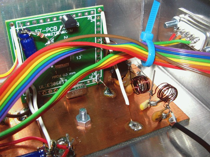 Here is a close-up of the
DDS.
Here is a close-up of the
DDS.
The pins of this IC are 0.3mm wide, and have 0.2mm clearance between
them. I exhausted all my extensive vocabulary of power expressions, in
three and a half languages,
while soldering them!
It's a real shame that so many nice ICs aren't available in
homebrew-friendly case styles.
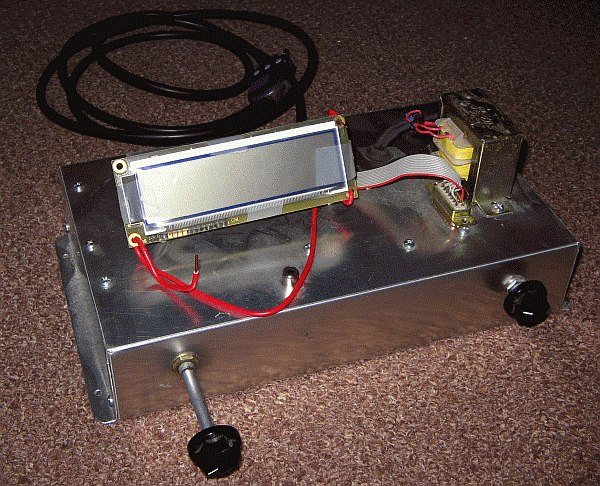
 The
top of the chassis looks pretty boring, when compared to an antique
tube radio. The only part mounted on the top is the power transformer,
and the connectors for the cabinet-mounted devices: A DB-15 for the
display, and
an RCA phono connector for the speaker.
The
top of the chassis looks pretty boring, when compared to an antique
tube radio. The only part mounted on the top is the power transformer,
and the connectors for the cabinet-mounted devices: A DB-15 for the
display, and
an RCA phono connector for the speaker.
The volume control potentiometer came with a very long shaft. The
encoder instead came with a very short one. If I ever build the nice
wooden cathedral-style cabinet, I will have to cut off the excess
length of the potentiometer's shaft, and make an extension for the
encoder's shaft. So is life. It's never fair! Some get it all.
Note
that the exact location of the two controls on the chassis' front side
is intended to look nice and balanced on that wooden cabinet I have in
mind... The display will sit in between the two controls,
slightly higher, and the speaker will go atop it. A cathedral cabinet
lends itself very well to such an arrangement.
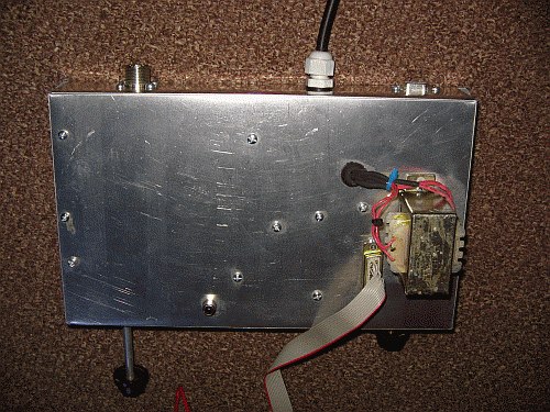
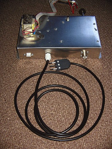 And here is a quick view of
the rear side.
And here is a quick view of
the rear side.
I used an SO-239 antenna connector just because all my HF ham radios
use them. So I can easily use the same antenna cables.
You
might wonder about the nice chassis? I made it from a single
piece of 1mm thick aluminium sheet. My technique is to draw the flat
design in CAD software, duly considering the material thickness when
designing the overlaps. Then I print the design on paper, stick the
paper to the aluminium sheet using double-sided tape, then I cut the
sheet using metal shears. Then I flatten the piece in a vise, to fix
the deformation caused by cutting. Then I use a hobby knife to cut
through the paper and into the aluminium, along all bend lines. Then I
drill all the holes through the paper and metal. Then I remove the
paper, deburr the edges, and bend the aluminium sheet, which is easy
and precise thanks to the knife cuts.
The four sides of the chassis are held together by sheet metal screws.
The firmware for
the PIC
compiles in PICBasic Pro, version 2.60. It can be edited with any text
editor, and then compiled. I included a lot of comments, so you should
be able to understand the program. It's long, but not complicated.
A lot of the length goes just into the bandswitching routines. There
are many instances of the same small actions, for each band, with the
proper values for each. It's not particularly elegant programming, but
it works fine.
The source code includes two encoder
reading subroutines. One is for encoders like the one I used,
which advance the 2-bit coding by a single step per click, going
through a full cycle in 4 clicks. The other is
for encoders that go through a full cycle of steps in each click. I
started developing this program using a mechanical encoder that used
the latter system. If you copy my radio but use such a
full-cycle-per-click
encoder, just remove the comment characters from the first encoder
routine, and comment-out the second one, that I left active.
The
constant "steps4k" can be tweaked to correct for frequency error of the
reference crystal. The "frecif" value can be tweaked if you
need
to shift the intermediate frequency.
My firmware uses 5kHz
frequency steps in all shortwave bands, and 10kHz steps in the medium
wave band, consistent with the standard in my part of the world. If you
want to copy my radio and use it in a country where the medium wave
band uses 9kHz stepping, you will need to modify the program
accordingly.
Also if you want to add any bands that I didn't consider, or change any
band limits, you need to edit the program.
So
there are a good number of reasons why you might need to edit and
recompile the program. But in case you can live with the values I used,
I'm including the compiled
hex file
too. You can directly burn this into your PIC, using any PIC
programming tool. This hex file also
contains the correct configuration of the PIC. If you recompile the
program, you might want to program the PIC only with the recompiled
program data, and burn the config word of this hex file into it,
because PICBasic Pro will most likely set the config word to something
different and incorrect, unless you edit the configuration files for
the PIC16F886 that come with the compiler.
The whole
radio is operated just with two knobs. The left knob controls
the
volume, and turns the radio on and off. The right knob is the
do-it-all: It can be rotated in steps, and pushed.
The radio has three main
operating modes: Tuning, Band Switching, and Memory. Short pushes on
the knob cycle through the three modes.
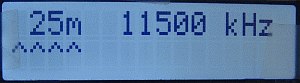
 In
tuning mode, the display shows the band and the frequency in
the
upper line. The second line is only used for the signal strength
indicator, which uses a single character, that grows and shrinks and
changes shape according to the signal level. 21 different signal levels
can be shown.
In
tuning mode, the display shows the band and the frequency in
the
upper line. The second line is only used for the signal strength
indicator, which uses a single character, that grows and shrinks and
changes shape according to the signal level. 21 different signal levels
can be shown.
When rotating the encoder knob, the frequency
changes in 5kHz steps in the shortwave bands, and 10kHz in the medium
wave band. When the limit of a band is reached, the radio automatically
moves into the next band. If moving up in frequency, it jumps to the
lowest frequency of the next higher band, and when moving down it jumps
to the highest frequency of the next lower band. When it reaches the
end of the highest band, it wraps over to the beginning of the lowest
band, and vice versa. This allows tuning continuously through all AM
broadcast spectrum, without having to care about the bands.
A short push on the knob takes us into band switching mode:
 The
band indicator gets underlined, and rotating the knob will cycle
through the
bands. While cycling up, we will land on the lowest frequency of the
next higher band, and while cycling down we land on the highest
frequency of the next lower band. Of course when reaching the highest
or lowest band the radio covers, it wraps around.
The
band indicator gets underlined, and rotating the knob will cycle
through the
bands. While cycling up, we will land on the lowest frequency of the
next higher band, and while cycling down we land on the highest
frequency of the next lower band. Of course when reaching the highest
or lowest band the radio covers, it wraps around.
Pushing the knob after having changed band takes us back into tuning
mode.
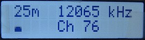 Pushing the knob two times,
starting from tuning mode, takes us into memory mode. It's
just like tuning
mode, except that the memory channel number is also shown.
Pushing the knob two times,
starting from tuning mode, takes us into memory mode. It's
just like tuning
mode, except that the memory channel number is also shown.
Rotating the knob cycles through the 100 memory channels.
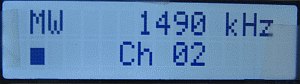 On
the medium wave band, MW is shown instead of the wavelength, because
this band stretches over a very broad range, from about 182 to 560
meters.
On
the medium wave band, MW is shown instead of the wavelength, because
this band stretches over a very broad range, from about 182 to 560
meters.
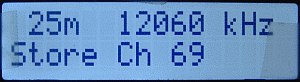 When
listening to a station in tuning mode, and wanting to store the
frequency in a memory, one simple gives a long push to the knob. Then
the display will show the currently selected memory channel, and its
content. Now one can rotate the knob to scan through memory channels
and their contents, until either finding a blank one, or finding an
unimportant one that one wants to overwrite.
When
listening to a station in tuning mode, and wanting to store the
frequency in a memory, one simple gives a long push to the knob. Then
the display will show the currently selected memory channel, and its
content. Now one can rotate the knob to scan through memory channels
and their contents, until either finding a blank one, or finding an
unimportant one that one wants to overwrite.
 Blank channels show up
like this.
Blank channels show up
like this.
Meanwhile
the radio continues receiving on the VFO frequency. A second long push
writes the VFO frequency into the selected memory channel. The display
will then show the newly programmed frequency. But if you decide that
after all you don't want to store the frequency, a short push aborts
the mission.
To erase a memory channel,
simply select it, in memory mode, and then give a long push to the
knob. The display confirms erasure by briefly saying "Blank".
This
single-knob user interface could be refined and embellished a lot, but
as it is, it
works quite well, so I never further developed it. And please excuse
the visible adhesive tape over the display, in these photos! I taped a
protective plastic sheet over the display, to keep it safe from damage
during
development, and that plastic screen is still in place, 13 years
later...
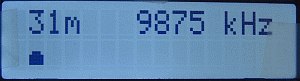
The radio, with the current firmware, covers the following bands:
MW: 530-1650 kHz
120m: 2300-2495 kHz
90m: 3200-3400 kHz
75m: 3900-4050 kHz
60m: 4400-5100 kHz
49m: 5800-6300 kHz
41m: 7200-7500 kHz
31m: 9250-10000 kHz
25m: 11500-12160 kHz
22m: 13570-13870 kHz
19m: 15000-15825 kHz
16m: 17480-17900 kHz
15m: 18900-19020 kHz
13m: 21450-21850 kHz
11m: 25670-26100 kHz
To
the best of my knowledge, this is the best compromise to get
all broadcast stations that transmit on legally assigned frequencies,
without getting too many non-broadcast signals.
After all, this is a broadcast receiver, not a communications receiver!
So it's undesirable to tune into SSB signals, Morse code, RTTY and
other digital modes, and so on. It's impossible to completely avoid
such unwanted transmissions, because some of the broadcast bands
partially overlap amateur and marine bands, and also because pirates
transmit wherever they please, without any regard for any band plans at
all.
I use this radio with the same multiband antenna I use for
my ham radio activities. It's a multiband antenna, consisting of four
dipoles, for the 80, 40, 20 and 10 meter bands, with capacitive loads
to also cover the 17, 15, 12 and 6m bands. The four dipoles share a
common balun and feedline. This antenna obviously was built for the ham
bands, and is very much out of tune on most broadcast bands, but since
broadcasters transmit with high power, it works fine. Any reasonably
long antenna should work with this radio. But a short
telescopic antenna won't be very good. The
sensitivity of this radio is well matched to a relatively
large
outdoor antenna, and is not enough for using a tiny antenna.
Anyway indoor antennas are pretty useless for shortwave these days,
because of the extremely high levels of interference created by
switching power supplies in a myriad of electronic equipment, from
computers and TVs down to LED lamps and cellphone chargers. We really
need to get our antenna as far away as possible from these noise
sources. For the same reason, a dipole antenna, with balun and coaxial
feedline, is a lot better then a simple long wire used against ground,
because in the latter case the whole long wire and the grounding wire
harness all pick up signals, and that includes wires that are very
close to strong noise sources. In the case of a dipole antenna with
balun and coax cable instead, only the antenna receives signals, and
the antenna is hopefully farther away from the noise sources.
Some
of my dear readers might ask what sense there is in painstakingly
building an AM shortwave world receiver, in this age of the
internet,
smartphones, and instantaneous, perfect, almost free worldwide
communication in audio, video, text and data? Well, it's pure
nostalgia, of course! I grew up in the glorious times when lots of
countries ran huge shortwave broadcast stations, transmitting worldwide
in many languages all around the clock. Such as the British
Broadcasting Service, Deutsche Welle, Voice of America, Radio Moscow,
Österreichischer Rundfunk, Radio Exterior de España, Radiodiffusione
Italiana all'estero, Radio Habana, Radio France
Internationale,
Radio Berlin International, The Voice of the Andes, and many more.
There were some years too in
which several Arab countries tried to outdo each other, and certainly
the whole rest of the world, in setting up and operating absolutely
huge transmitters. One megawatt of transmitter power, into a 15dB gain
antenna array, resulting in roughly 30 megawatts of EIRP, was not
unheard of. I couldn't understand Arabian languages, but the music they
transmitted, often for long times, was certainly nice. It was
particularly funny to contrast the views expressed by the official
stations of countries on opposing sides of the iron curtain. My
country, Chile, was a dictatorship in those years, and it was great fun
to listen to the news published by certain politically motivated
stations, about streams of blood flooding the streets, terrible
hardship of the people, and so on, while living here and knowing better
how things really were. Sure, not everything was right and ideal here,
we all knew that, and some people did suffer, but it certainly wasn't
like those radio stations told the world, and I took those news
programs as comical acts. I miss them!
Unfortunately
we have lost almost all of this juicy, funny, rich shortwave broadcast
scenery. Most of those big stations are gone. A few try to cling to
life, but have a hard time. The only really big international
broadcaster these days is China Radio International, which has
many
simultaneous signals, in various languages, with high power, although
most is in
Chinese, and again I'm limited to just listening to the music they
transmit. They also transmit Chinese lessons, but I'm too old to learn
Chinese, as much as I would like to do so. Radio Habana is still on,
but the transmitter serving my area
has had a serious modulator problem for years, so the transmissions
are impossible to understand, and strangely the people running that
station seem to totally lack any interest or ability in repairing that
transmitter... At the same time, their famous opponent, Radio Martí
from Florida, USA, is going strong, keeping some of the old days'
political propaganda style alive. The world divided into good
and bad, right and wrong, black and white, top and down, so childish
and simple that it is endearing... I also often hear Radio Romania
International, with nice programs about their country, and sometimes
various much smaller stations, like Radio Cultura from Mexico, and a
guy from the USA who bought one of the large transmitting stations and
is broadcasting a mix of paid-for religious and colorful philosophical
programs,
and in the remaining time retransmits internet radio stations.
My
main language is German, and I'm a bit sad that there is absolutely no
German-language broadcasting on shortwave now. At least I haven't heard
any in ages. Back in the 1980's the Deutsche Welle was a big player,
and I
often listened to them. Gone with the wind...
So, some of
the old glory of shortwave broadcasting remains, but it's a lot less
than
there once was. Still I enjoy my evening bedtime shortwave listening
sessions. Listening to anything, even in Chinese, mixed with the
mysterious noises of nature, atmosphere and the cosmos, has a very
special
charm.
And on medium wave, here in Chile in the evenings I
hear a huge lot of Argentinian stations, and also quite a few Chilean
ones. Rarely any others, but occasionally I have
heard Falklands Radio, at the very low end of the MW band, or
some Brazilian station. On the MW band I get some Tango
programs, and even some occasional Radio Drama! But MW
listening in the evenings is always affected by deep fading,
and since several
stations share each frequency, I hear one station for a while,
then it will fade out and another will rise and replace it. It has its
own charm!
Back in the 1980's, WWV and WWVH were very weak here,
compared to the huge signals of many big broadcast stations. Nowadays
very often WWV and WWVH are stronger than the broadcasters! I
don't think that WWV and WWVH increased their transmit power so much,
so this change seems to show that in average SW broadcast signals are
far
weaker nowadays than they were 40 years ago. The megawatt stations are
all gone.
I have over two dozen antique tube radios in my collection, most of
which can receive short waves. As a ham, I also own several HF
transceivers. But what receives short wave broadcast stations best is
my homebuilt 15-Band World Receiver! The combination of rock-steady
frequency stability, optimal bandwidth, high selectivity, 5 kHz notch
filter, 100 memories, and tuning range limited to the
broadcast bands, beats each of my other receivers,
in performance and convenience.
I don't expect any of my readers to build an exact copy of my radio.
The problems would start with procuring the exact same parts! But if
some of you find usable ideas or tips in my design, such
as the 5 kHz notch filter, or how to control the
AD9951 DDS chip, then it made sense publishing this page!
Back to homo ludens
electronicus.