T12 Soldering Iron Temperature Controller
 When I
started in electronics, temperature-controlled soldering irons were
very expensive. Almost every electronician, and particularly poor
students like me, used some cheap and plain soldering iron instead, and
the more clever students hooked it up to a dimmer, to at least have
some degree of control over the temperature. But of course
the iron would cool down while soldering large items, and heat up a bit
too much when
left unused for a while.
When I
started in electronics, temperature-controlled soldering irons were
very expensive. Almost every electronician, and particularly poor
students like me, used some cheap and plain soldering iron instead, and
the more clever students hooked it up to a dimmer, to at least have
some degree of control over the temperature. But of course
the iron would cool down while soldering large items, and heat up a bit
too much when
left unused for a while.
Eventually I got rich enough to buy one of those very
expensive temperature-controlled Antex soldering irons, which
has served me well for roughly 35 years so far, going through several
dozen tips. But the time came when I got so immensely rich that I
wanted the luxury of a second
temperature-controlled soldering iron, so that I could keep one with a
tip for through-hole soldering, and another with a small SMD tip,
instead of having to constantly switch tips on a single iron. There
just was one
problem: While I got a lot richer than I was as a student, I never
ceased to be a cheapskate, so I didn't want to buy a second Antex!
Nowadays there are many Chinese soldering irons, and some of them are
actually good enough to use, although some others aren't...
Particularly I grew fond of the T12
soldering tips. These exist in many sizes and shapes, and they have a
thermocouple built right into the tip, which allows good temperature
control. They also have the heater built into each tip, which seems
like an overkill, but they are still cheap enough to not worry
about this. And in any case, having the heater in the tip provides the
best possible thermal conductivity, and thus a quick-heating, powerful
tool.
The heaters are designed for maximally 24V, and they run at over 60W
at that voltage. Even with as little as 11V they get hot enough to
solder not-too-big items. So I saw the chance to make a dual-use
soldering iron: In my lab it can serve as a second soldering iron for
SMD use, while in the field it can be used as a pretty versatile
battery-powered soldering iron, capable of soldering connectors and
large wires!
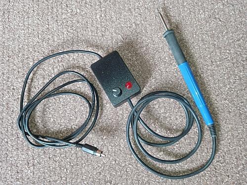
The Chinese makers sell a variety of controllers and power supplies for
the T12, but I chose to make my own, since it's easy, cheaper, and
gives me all the control to make exactly what I want. So I bought a
selection of T12 soldering tips, a handle for them, and I made
a little portable controller. The power input connector is an RCA phono
plug, which I use as my standard low-voltage supply connector for
devices
consuming up to about 3A.
There are both digital and analog controllers available. I personally
don't see an advantage in a digital one, because anyway the
thermocouples in these soldering tips aren't precise enough to allow
accurately measuring the temperature - even less so given that there is
usually no cold-junction compensation, and it would be unduly hard to
implement one. So all that's needed is a circuit that stabilizes the
temperature, and the user turns a knob to set the temperature so that
the iron solders well with the particular tip and solder type used. An
analog circuit does this best.
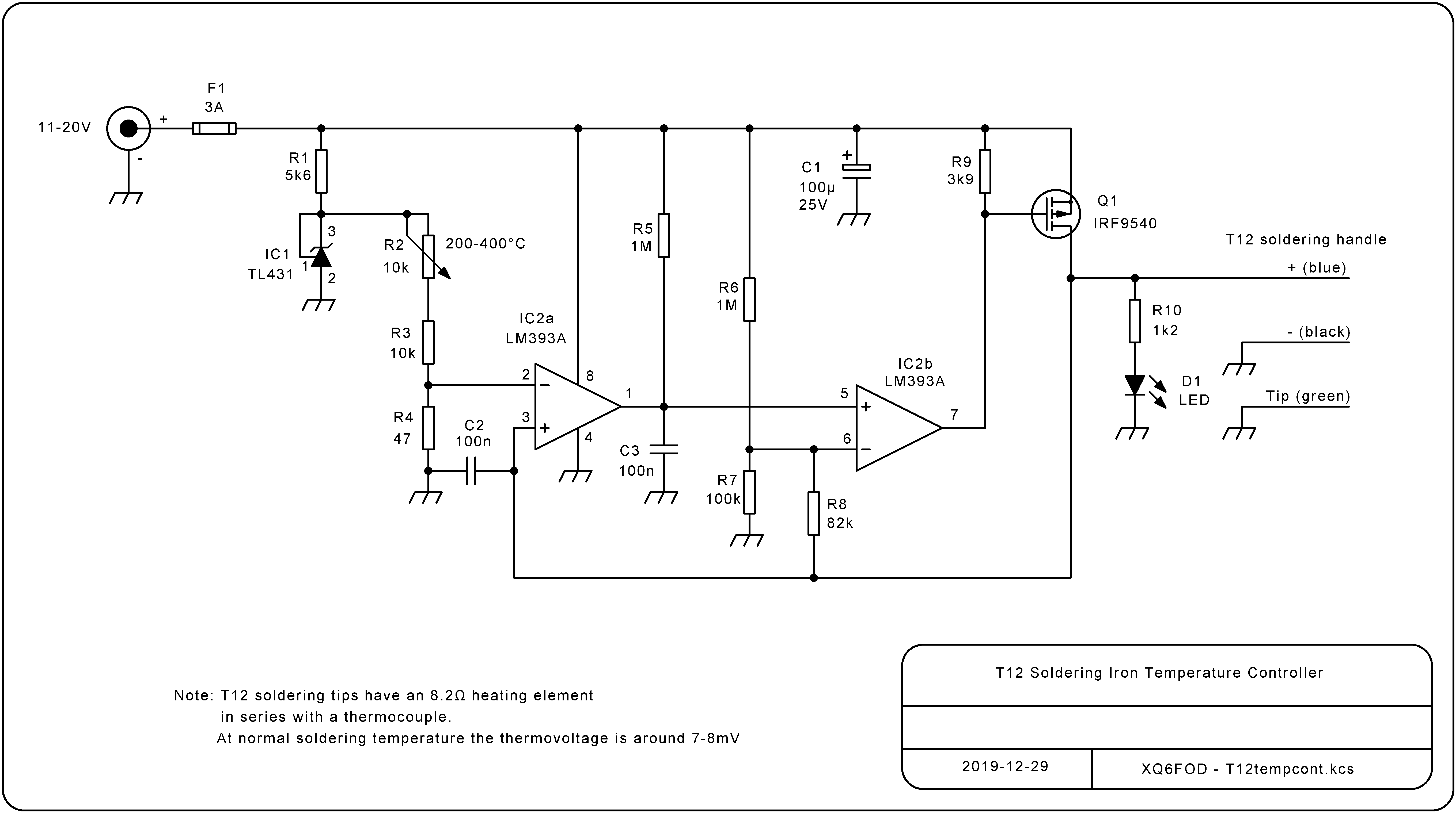
Many little analog controller boards are available that use variations
of a circuit based on the LM358 dual op amp. I had a look at
this circuit, but found it a bit stupid, because it is designed to
defeat the
LM358's totem-pole outputs, instead of using them to
advantage. In a circuit like this, actually open-collector outputs are
more suitable, and a comparator is also better suited than an op amp.
So I modified the "industry standard" circuit to use an LM393A dual
comparator, which features open-collector outputs, and resulted in
saving several components. This is the
result:
As usual with my schematics, you can click it to get a high resolution
version for printout.
The circuit is very simple, but its way of operation isn't immediately
obvious, so here is a functional description. To easily understand it,
you need to keep in mind that the LM393A has
open-collector outputs, and that the T12 soldering tips have a
thermocouple connected in series with the heater element.
When the circuit is first turned on, C3 is at zero charge, so IC2b gets
0V at its positive input, but some higher voltage at its negative
input, and thus its output is in logic low state, which means that the
open-collector output transistor is on. As a result Q1's gate gets
pulled to ground level, Q1 turns on, this applies the full input
voltage to the soldering iron's heater, and also lights the LED. In
addition the positive input of IC2a gets pulled up very high, way above
its negative input, so that this comparator sets its output to logic
high, which means turning its output transistor off.
As a result C3 can slowly charge through R5, until the voltage on it
exceeds the voltage on IC2b's pin 6. This voltage depends on the supply
voltage, but since the charging speed of C3 also depends on the supply
voltage, the time it takes for C3 to charge up to this level is
unaffected by the supply voltage (a ratiometric circuit). For example,
at 15V supply voltage
pin 6 will be at roughly 8.5V, which is given by the voltage divider
action between R7 pulling down to ground, and both R6 and R8 pulling up
to 15V.
When C3 exceeds this voltage, IC2b will change state, turning off Q1.
Now the drain of Q1, which is the positive side of the soldering tip's
heater and thermocouple series pair, will go to a very low voltage,
that
depends on the temperature the thermocouple has reached. It's of the
order of just a few millivolt. This pulls down the voltage on pin 6 to
only about 0.65V, making IC2b operate as a very strong Schmitt
trigger. Also the very low thermocouple voltage gets directly to pin 3
of
IC2a. C2 is there simply to bypass any RF interference that the
soldering
iron, wiring and circuit might pick up, and it is important
to locate this capacitor close to the IC, and sharing the same ground
point as R4. Pin 2 gets an adjustable, very low reference voltage,
produced by the variable voltage divider R2-R3-R4, from a regulated
2.5V reference created by IC1 and R1. The voltage at pin 2 can be
adjusted between aproximately 5.9 and 11.7mV. This equals the voltage
generated by the thermocouple of a T12 soldering tip for typically a
200-400°C range of temperatures.
As long as the soldering tip is at a temperature lower than the set
value, IC2a will
turn on its output transistor when Q1 turns off, very quickly
discharging C3 until its voltage falls below the 0.65V present on pin
6. Then IC2b will again turn on its output transistor, turning on Q1
and the heater element, which will again raise the voltage on pin 3,
turning off IC2a's output, allowing C3 to begin charging
again, to the 8.5V to which pin 6 has returned.
So, while the soldering tip is still colder then the selected
temperature, it will be powered with the full input voltage almost
continuously, only with very short interruptions to sense the
temperature. These dropouts are too brief to see them at the
LED, which visually stays continuously lit. The soldering tip heats up
pretty much as fast as possible at the present input voltage. C3 will
have a sawtooth wave on it, with a frequency of roughly 10Hz and a p-p
value of roughly one half the supply voltage.
When the tip has reached the desired temperature, the
situation changes: When
Q1 turns off, the thermocouple in the tip generates enough voltage to
keep pin 3 above pin 2. This keeps the output transistor of IC2a off,
allowing C3 to keep charging. So Q1 will remain off, for as long as
needed until the thermocouple has cooled below the set point. At that
time IC2a will turn its output transistor on, discharging C3, and this
will restart heating.
If there was an instantaneous thermal coupling between the heater and
the
thermocouple, the circuit would now operate with a fixed HEATER ON time
of about 0.1 second, and a variable HEATER OFF time as needed
to keep the temperature stable. But since there is some time lag
between the heater and the thermocouple, circuit operation gets a bit
slower, typically producing ON times of about 1 second (actually
composed of individual 0.1 second pulses with brief drops between
them), and OFF times that can reach up to 10 seconds or so. The LED
allows observing this clearly.
 This
circuit works very well, but since IC1a compares such small input
voltages, it's critical to build it properly: You need to make sure
that the ground current flowing between the power input and the T12
negative wire doesn't cause any voltage drop affecting IC1a. The
easiest way to do this is to make a star ground point, to which 4
things are connected: The negative supply input, the negative
lead of the
T12, the ground of the tip, and a wire that goes to the
ground of the rest of the circuit. Ideally the LED negative
should also be connected to this star ground, or directly to the T12
negative. If you get the ground wiring wrong, the circuit will be
somewhat unstable, with the LED flickering a lot, or staying on and off
for longer times than it should, but even then you should get a pretty
decent temperature control of the tip.
This
circuit works very well, but since IC1a compares such small input
voltages, it's critical to build it properly: You need to make sure
that the ground current flowing between the power input and the T12
negative wire doesn't cause any voltage drop affecting IC1a. The
easiest way to do this is to make a star ground point, to which 4
things are connected: The negative supply input, the negative
lead of the
T12, the ground of the tip, and a wire that goes to the
ground of the rest of the circuit. Ideally the LED negative
should also be connected to this star ground, or directly to the T12
negative. If you get the ground wiring wrong, the circuit will be
somewhat unstable, with the LED flickering a lot, or staying on and off
for longer times than it should, but even then you should get a pretty
decent temperature control of the tip.
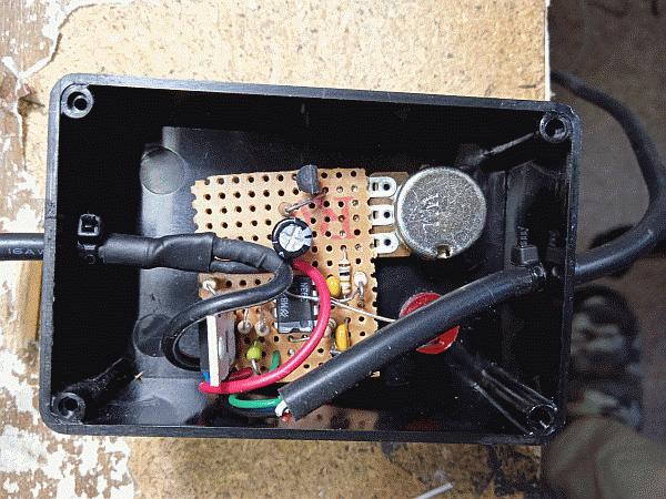
I built the circuit on a little scrap of perfboard, the kind
that has a copper pattern like a protoboard. I keep finding this the
most practical way to build single simple circuits like this. My star
ground point is at the lower left corner of the board. I used one
power trace to solder first the negative input, then the negative of
the T12, then the ground of the T12, and then the power trace runs on
to the
rest of the circuitry.
Note the cable ties placed tightly around each cable entering the box,
as strain reliefs.
 Then I
put some globs of hot melt glue around those cable entries, also around
the LED (I used one of those nice-looking jumbo LEDs, but that's purely
a matter of taste), and also at two corners of the board, while a third
corner is supported by the potentiometer. This immobilizes all of the
stuff inside the box.
Then I
put some globs of hot melt glue around those cable entries, also around
the LED (I used one of those nice-looking jumbo LEDs, but that's purely
a matter of taste), and also at two corners of the board, while a third
corner is supported by the potentiometer. This immobilizes all of the
stuff inside the box.
There isn't much to say about the components, since these are all very
common and totally standard. The MOSFET doesn't need a heatsink. It
stays cold even without one. I used carbon film resistors having a 5%
tolerance, since that's good enough. Also I used ceramic multilayer
capacitors for C2 and C3. In the case of C3, a film capacitor would
give better stability of the oscillation frequency, but such stability
isn't needed at all, so I used the cheaper and smaller ceramic
capacitor. And
the fuse is a subminiature one, which has the size and shape of a
quarter watt resistor. It's soldered in place, because I
don't expect it to ever blow. That's the optimist in me, you know...
In my lab I power this soldering iron from 13.8V, because being a radio
amateur I have a big 13.8V supply constantly on. At this voltage, the
T12 heats to soldering temperature in about 30 seconds, and is powerful
enough for all PCB and connector work except the biggest
stuff. And when going into the field, I use a lithium ion battery made
from four 18650 cells in series, with a ready-made battery management
circuit that includes cell balancing. At the 16V provided by nearly
full cells, I can solder even coax connectors and thick wires.
I rated the circuit for 11 to 20V, because below 11V the heating power
of the T12 tips
is too low, and above 20V there is some theoretical risk of damaging
the MOSFET gate. If you really want to go to the full 24V rated for the
T12 tip, you might want to use a MOSFET with a 30V gate rating instead.
Or just risk it... The gates usually don't break down with such a
slight overvoltage. But if you manage to destroy your MOSFET, don't
tell anyone that I suggested this! :-)
In any case, I think that hardly anyone will need the full power a T12
tip develops at 24V.
Back to homo ludens
electronicus.