Ferrite core loss meter
When building switching power supplies and similar circuits, the design
of the transformers is crucially important. While designing
these, it's essential to decide how much flux density to allow in the
cores, because if it is too high, the cores will overheat, or at least
cause more loss than is acceptable. And if it's too low, then the
transformers will require too many turns, which forces the use of
thinner conductors, dramatically increasing the losses in the wire, and
also increasing the leakage inductance, which can become the limiting
factor to power throughput.
Many people face the difficult question of just how much flux density
is acceptable for a given core, at a given frequency. It can be
calculated rather easily, but that requires good, reliable data about
the core used, and experimenters often can't get this, because the
cores were salvaged from old equipment, and the manufacturer and
ferrite type are unknown.
There is a very practical way to find out how much flux density to
allow, and thus how many volts per turn or turns per volt to use. It's
winding a few turns of wire through the core, applying voltage at the
intended frequency, and measuring how much power the core consumes.
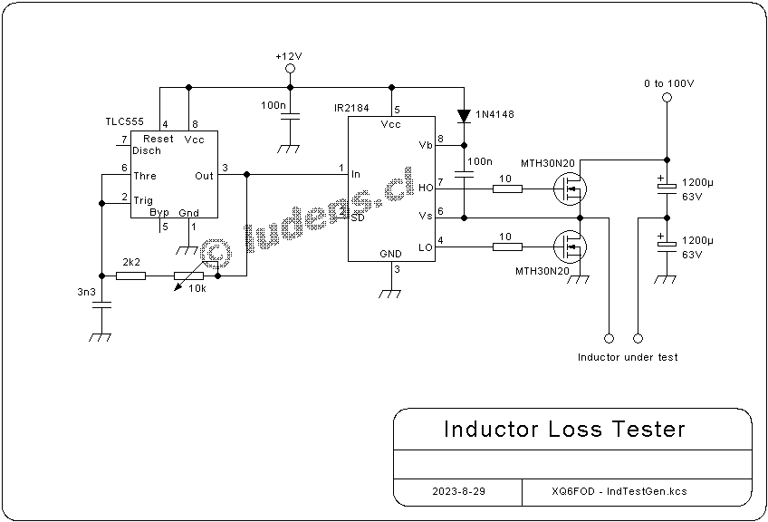
To do this, one needs a square wave source of adjustable
frequency and voltage, that can provide considerable current. It's very
easy to build one, so I did:
 There is a CMOS type 555 timer,
configured as a 50% duty cycle oscillator, that covers a frequency
range of about 17 to 90kHz, with the component values shown.
This oscillator controls a half-bridge MOSFET driver, which
drives two MOSFETs in a half bridge configuration. The timer and driver
ICs are powered from a fixed 12V source, and consume only a few mA,
while the half bridge is powered from a variable voltage,
current-limited bench power supply that has its own voltage and current
meters, but of course one can use any other suitable power source, and
use plain multimeters to measure the voltage and current.
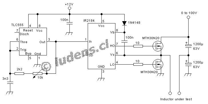
There is a CMOS type 555 timer,
configured as a 50% duty cycle oscillator, that covers a frequency
range of about 17 to 90kHz, with the component values shown.
This oscillator controls a half-bridge MOSFET driver, which
drives two MOSFETs in a half bridge configuration. The timer and driver
ICs are powered from a fixed 12V source, and consume only a few mA,
while the half bridge is powered from a variable voltage,
current-limited bench power supply that has its own voltage and current
meters, but of course one can use any other suitable power source, and
use plain multimeters to measure the voltage and current.
The idea behind this circuit is that the MOSFETs, electrolytic
capacitors, and the test winding of just a few turns of thick wire have
very low loss, so that almost all of the power consumed from the bench
power supply is due to ferrite core loss.
When testing a large ferrite transformer at high flux density, the test
winding, MOSFETs and capacitors might take a pretty large (magnetizing)
current, which has a triangular wave shape, but this is a reactive
current that simply bounces energy forth and back between the
capacitors and the inductor. The supply current will remain pretty low,
since the bench supply only needs to provide enough power to overcome
the losses. This allows using a pretty low current bench supply.
The effective AC voltage this circuit applies to the inductor under
test is a tad less than one half of the supply voltage, since it's a
half bridge. The "tad less" is due to the small dead time between the
conduction times of the two MOSFETs, and any voltage drop in the
MOSFETs' RDSon and in the capacitors' ESR. If high accuracy is desired,
it's best to measure the actual voltage applied to the test winding, by
means of an oscilloscope. Otherwise it's OK to just take half the
supply voltage as the AC voltage applied to the coil.
One can use this circuit to build a loss table of a given core, by
applying several frequencies, each at several levels of volt per turn,
marking the points on a paper graph or in a spreadsheet, and then
drawing the graph from them.
When comparing loss measured with this circuit to the loss figures
published by the manufacturer of your core, you need to consider two
things: Firstly that this circuit measures the loss with a square wave,
which is realistic for switching power supply use, while manufacturers
usually give loss data for sine waves only. Due to the harmonic content
of a square wave, the loss with a square wave is higher than that with
a sine wave, at a given flux density and frequency. And the other thing
is that some manufacturers tend to be quite optimistic when
writing datasheets! Others instead are honest. And this is a
very good reason for making one's own loss measurements, instead of
relying purely on manufacturer data - even when such data is actually
available!
When designing a specific circuit, one can determine the allowable volt
per turn number by simply adjusting the frequency and voltage to the
desired values, letting the circuit work for 10 to 20 minutes or so,
and then measuring or even just feeling the temperature attained by the
core. When doing this, it's good to also feel or measure the
temperature of the MOSFETs and capacitors, just to make sure that
actually most of the power measured by the bench supply is going into
the core, and not into those other parts! Then one can change the
applied voltage or frequency, watch on the supply's meters how much
more or less power goes into the circuit, find the level that seems
reasonable, and again let it run for some minutes to feel how warm the
core gets.
Of course the voltage, number of turns, frequency and core dimensions
can be used to very easily calculate the flux density in the core,
using the method explained in Transformers and Coils.
If you build this circuit, of course you don't need to search
for the exact, obsolete MOSFETs I used. Choose your own
instead, using any that have a nice low RDSon. Mine have 80mΩ, but
lower would be better. Nowadays there are many MOSFETs with much lower
RDSon, so pick any of those. They should also have a high enough
voltage rating for the tests you need to do. Since you can even use a
single-turn test winding on your core, you don't need a very high
voltage capability. In fact I use just a 0-30V bench supply, so that
the voltage capability of my MOSFETs is overkill, and that of my
capacitors too. But when testing very large cores at high drive levels,
I sometimes get to the point where my MOSFETs get noticeably warm, so
it would be better to use MOSFETs with a lower RDSon than the ones I
used. Also the capacitors of the value shown are only good to about 5A
of coil current. This has been enough for me, but if you need to test
any enormous cores, it would be advisable to use several such
capacitors in parallel.
When building the circuit, the MOSFETs and electrolytic
capacitors should form a compact loop with very short conductor
lengths. Leave the MOSFETs without heatsinks, so that you can feel it
if under some condition they dissipate a significant amount of
power. The rest of the circuit is rather uncritical. I
actually just soldered the MOSFETs and capacitors together in a fresh
air 3D arrangement, and built the rest of the circuit on a protoboard.
Don't replace the CMOS 555 by a non-CMOS one, because the
non-CMOS version will not produce a clean 50% duty cycle. That's
because the non-CMOS versions have asymmetric saturation voltage of the
output.
If you prefer, you can also just use the general idea behind
this circuit, and use a square wave generator and MOSFET driver of your
own design.
It works really well, and shows that a simple gadget can be
very useful. I like very much getting a good feel, with my very own
fingers, of how warm the core I want to use really gets when applying
the voltage per turn and the frequency that I intend to use. Of course
one has to remember that in practical use it will get warmer, because
the definitive windings generate their own heat, and also reduce the
air flow around the core, and the ambient temperature inside the
equipment might be considerably higher than that in the room. So
"fingertesting" has its limits, but pretty accurate core loss
measurement is easy by simply reading the voltage and current going
into the bridge.
Back to homo ludens
electronicus.