The Kenwood TS-450 and its sibling, the 690, are great radios. But they aren't perfect. Improvements are certainly possible. Here is one!
These radios have a "packet" connector on the rear. This connector provides all necessary connections for digimode operation: Audio output, audio input, a special PTT input that mutes the microphone, and also some additional signals such as a squelch output.
There are a few problems with this connection. One is that the pin labeled as audio ground return is actually not a ground at all. It's only grounded through a 1nF capacitor. The audio input impedance is 10 kiloohms, and if you return the audio ground through that pin (12), a very bad audio response will result, that rolls off at a rate of 6 dB per octave over the whole audio band. The solution to this problem is of course trivial: Use either pin 8 or pin 4 as ground return. These are true ground pins.
Another problem is that the ground pins are grounded only through a very thin circuit board trace. The first time I had some strong RF field in the shack, the cable picked up enough RF to burn out this trace. The fix is easy enough: Solder a decently sized wire over that trace, and also try to get the RF field in the shack low enough. Of course, DC current flowing on that cable due to ground loops has to be avoided also.
But the third problem is obvious, and often goes undetected by users: The audio output provided on pin 3 of this connector is awfullydistorted! This signal comes from a very simple, one-transistor buffer amplifier, that employs no negative feedback and works at a pretty high signal level. That's a great recipe for distortion. It seems that a Kenwood engineer designed this simple amplifier stage just to drive the next stage of the "db amplifier", which is just a simple little amplifier that brings the audio up to a level high enough to drive the radio's secondary meter function in RX, which displays the audio level in dB relative to the nominal maximum level. For such a purpose, of course, distortion doesn't matter at all, and that simplistic amplifier is perfect. The trouble is just that when they added the packet connector to the radio, they stole the RX audio from this amplifier, not noticing or not caring for the fact that the audio here is highly distorted, and that they very handicapping the radio's usability for digimodes by doing this!
In Kenwood's defence, I have to say that for packet radio, which was the main intended application of that connection, such distortion doesn't cause a really big problem. Packet signals are rather wide, so they were not placed too close together in the bands, and it was common practice to use narrow IF filters to separate them, as the TNCs of the day weren't too good at picking out one signal from among several sharing the audio bandwidth. So, a little intermodulation didn't cause much harm.
Not so with modern digimodes. Many of these are very narrow banded, and are placed very close together. Typically two dozen PSK31 signals will be squeezed into the radio's IF and audio bandwidth, and the sound card has to separate them. If the radio mixes up all these many signals and causes a fog of intermod products, this process is greatly hampered, and one just can't work the weak stations between stronger ones. Many operators have discovered that the TS-450 performs much better on digimodes using the headphone or external speaker outputs, rather than the packet connector. The distortion on that packet output is the reason.
I like to use that rear panel connection, because then I can leave all connectors plugged in, including the microphone and external speaker, and work digimodes and voice alternately or mixed, without any configuration change. So I decided to modify my TS-450 to fix the distortion problem.
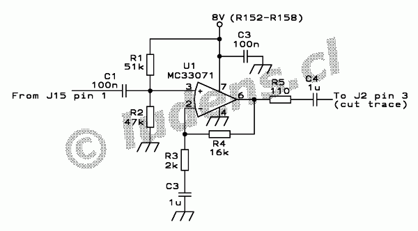
The audio is clean at the point before that simple one-transistor amplifier. That's the point that goes to the top of the volume control. But this point should not be simply wired to the packet connector, because it has a pretty low level, too low to properly drive a sound card line level input. So I built a new buffer amplifier, that takes this clean signal and raises it to about the same level the one-transistor amplifier provides, which is fine for sound cards.

It's just an operational amplifier wired up as a noninverting amplifier with a voltage gain of about 9. I used an MC33071, because it was the more suitable among the two types of single op amps I had at hand. A wide range of op amps will work well in this application. Mainly you have to make sure that your chosen candidate can operate properly from a single supply of 8 volts. This application doesn't pose any particularly high demands on noise performance, bias stability, offset, gain bandwidth product, slew rate, and so on.
The resistor values I used don't need to be copied exactly. There's nothing too critical. Using values within +/-20% of the stated values is fine. I used multilayer chip capacitors, so there is no polarity. If you happen to use electrolytics for the 1uF ones, connect C4 with the positive pole to the left, and C3 obviously with the positive pole up.
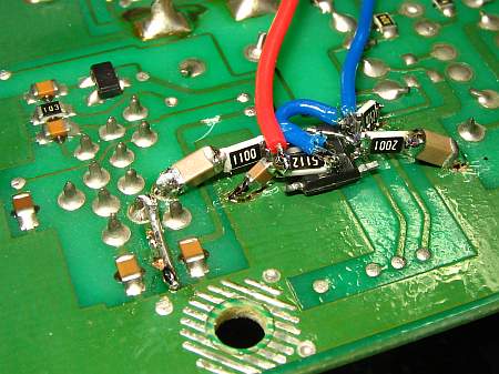
 I assembled
this circuit on the underside of the radio's IF board, in an empty area
close to the packet connector. I used SMD 3D NSM technology. That
stands for Surface-Mount
Devices, 3-Dimensionally arranged and Not Surface-Mounted. The
IC actually sits flat on the board, but only its ground pin was left in
its original shape and soldered to the ground plane. The other pins
were bent into a horizontal position. The other grounded components
were soldered to the ground plane too, but in an inclined position so
that their other ends end up in clear air. The output coupling
capacitor was soldered directly to pin 3 of the packet connector, in
the same fashion. The other nongrounded parts were soldered between
them. Two resistors ended up on top of the IC, and some wires are on
top of that. One of the beauties of SMT parts is that you can do this kind of multilayered construction,
without running out of space under the board! This board mounts about
5mm or so away from the shield plate, and that's plenty to accomodate
this three-dimensional construction style of additions!
In the foreground you can see the wire patch over the trace that got burned when the packet cable caught some RF, many years ago.
And above the 110 Ohm resistor you can see where I cut the trace that originally brought the distorted audio to pin 3 of the connector.The blue wire brings in the low level audio signal, and the red one brings in the 8V. They land on the board a few cm away from the new buffer amplifier.
After the modification, my radio performs much better on the digimodes, specially in regard to pulling out weak stations from a crowded piece of spectrum. The waterfall display now looks very much cleaner, with all that intermod from strong stations simply gone! The audio waveform now looks symmetric, while originally the negative excursions were much larger than the positive ones. And when listening to the audio on the computer speakers, now it sounds clean, while before there was an obvious harsh distortion on it.
This modification might be applicable to some other Kenwood radios of that time too, but I haven't checked their schematics.
Back to the homo
ludens electronicus
page.